1. Linear bearings and other linear motion guidance components
Linear motion guidance components are the most commonly used components in automated motion mechanisms for transferring, handling, positioning and assembly.
Here we will compare linear bearings, slide guides and oil-free bushings and focus on the use of linear bearings.
(1) Comparison of linear bearing characteristics
An approximate comparison of the characteristics of the three linear motion guidance components is summarized in the table below.
| Types | battery capacity | Coefficient of friction | Guide accuracy | Environmental Resistance | Maintainability | Price |
| Linear Bearings | △ | O | O | △ | △〜○ | Low price |
| Linear Guides | O | O | O | △ | △〜○ | High Price |
| Self-lubricating bushings | △ | × | △ | ○ | ○ | Moderately priced |
Below is an introduction to the relationship between the above characteristics and construction.
(2) The correlation between the characteristics and construction of linear guiding parts.
1. Performance differences in relation to load capacity:
- Linear bearings and self-lubricating bushings.
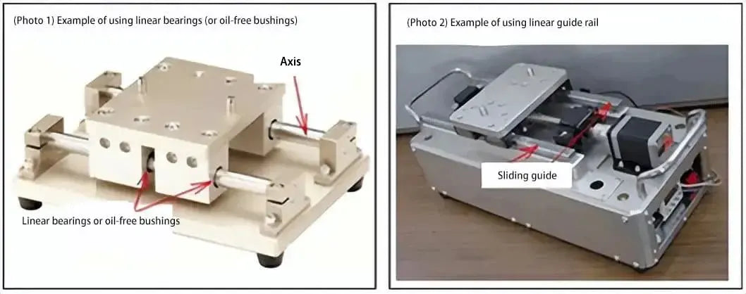
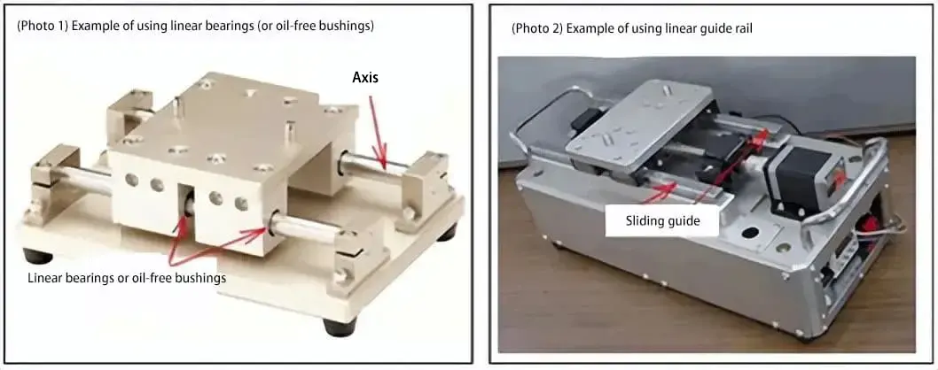
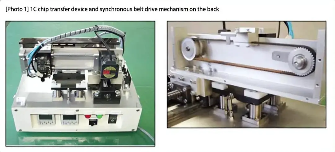
a) Movable components with linear bearings or self-lubricating bushings are generally mounted on a shaft (guide rail) supported by support structures at both ends to fulfill their movement function. When transporting large loads, the axle is easily deformed (see (photo 1)).
(In addition, when guiding linearly vertically, a simple structure that ignores the load problem can be used, as the shaft does not need to support the load of the moving component.)
- Linear guides
b) The moving components move on fixed guide rails mounted on the base, which have excellent load-bearing characteristics (see (photo 2)).
Linear bearings and self-lubricating bushings => Linear movement on a shaft (guide rail) fixed at both ends => linear movement with light to medium loads.
Linear guides => Linear movement on guide rails fixed to the base => linear movement with light to heavy loads.
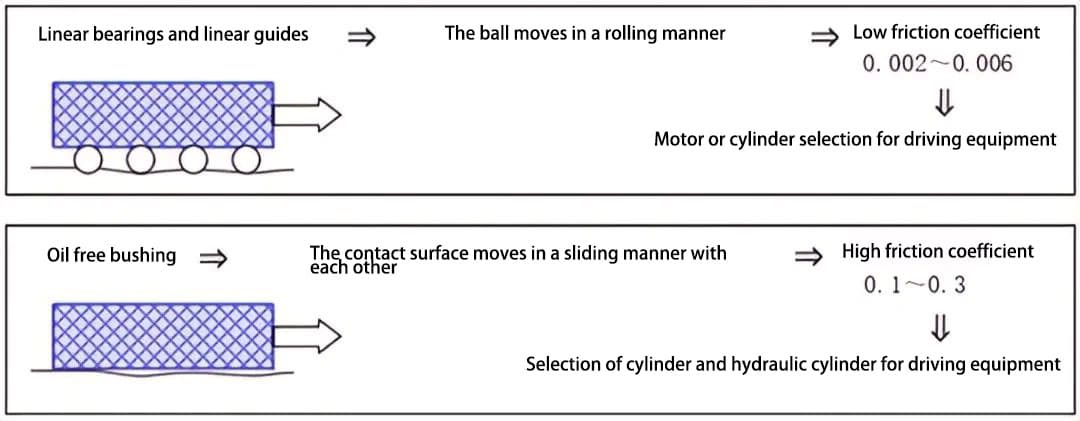
2. Performance differences in relation to the coefficient of friction:
Here, differences in the guided sliding method (rolling or surface sliding) determine the performance differences. The difference in friction coefficient is directly related to the selection of the drive actuator.
a) Small frictional resistance = small frictional force = can be driven by a small torque motor = rotary motion can be converted into linear motion.
b) Large frictional resistance = large frictional force = requires large torque or thrust drive = can be directly driven by a linear cylinder.
■ Usage precautions
The size of the friction coefficient affects the capacity of the drive equipment and the amount of heat generated during operation. Plain bushings are not suitable for continuous high-speed operation with high heat generation.
When using a cylinder, the start/stop speed cannot be controlled as with an engine. High-speed operation and vibration suppression can be achieved by installing flexible braking mechanisms such as shock absorbers and shock absorbers.
3. Performance differences regarding guide accuracy:
Basically, performance is determined by the clearance between the bearing and the guide rail.
a) In the case of linear bearings, a cylindrical shaft is used as a guide rail, and the clearance between the bearing and the guide rail is set as “interference fit: g6” or “transition fit: h5”, and the bearing slides in a state of minimal “gap”.
b) For linear guides, dedicated guide rails are used and high-precision bearings and guide rails with small clearance (0-3 μm) or pressurized type (-3-0 μm) are paired.
c) Compared to linear bearings, self-lubricating bushings have greater clearance between the guide rail (shaft), resulting in lower guidance precision.
■ Usage precautions
The contact states between the ball and the guide rail are different for linear bearings and linear guides. Linear bearings have a point contact state, where the contact part locally supports a large load.
The contact portion between the guide rail and the ball bearing in the linear guides adopts a groove shape, allowing the ball to be in a state of surface contact with the surface of the guide rail, and therefore the contact load is dispersed.
There are also differences in the load-bearing capacity characteristics between the two with regard to the contact state in the sliding portion. ((Figure 1) and (Figure 2))
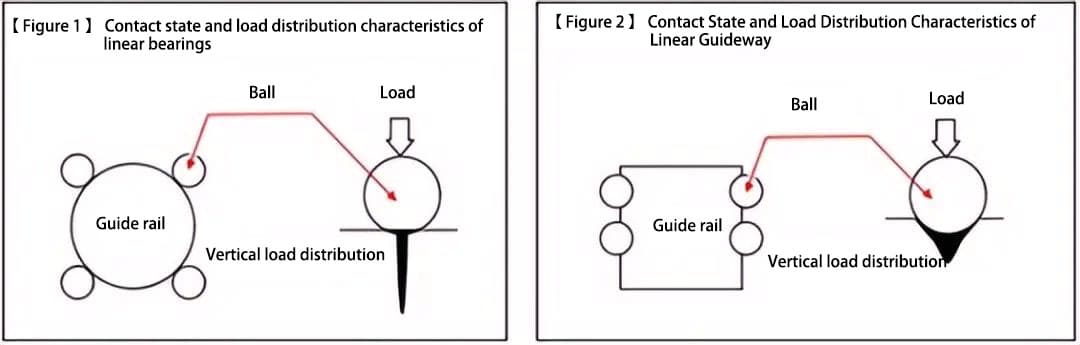
- Linear bearings => point contact state => uneven vertical load distribution => not suitable for high load conditions.
- Linear guides => state of contact with the surface => dispersed vertical load distribution => can withstand relatively high loads.
4. About environmental resistance and maintainability:
This difference in performance is determined by differences in the constituent materials.
a) Linear bearings and linear guides can achieve long-term reliability due to the effect of lubricating oil (grease), so the working environment cannot exceed the environmental resistance index of lubricating oil.
b) Self-lubricating bushings are generally used in environments where there is no lubricating oil and have good environmental resistance and ease of maintenance.
2. Distinction between linear and flanged types
Below we explain the differences in the external shapes of linear bearings (linear type and flanged type) and the care to be taken during assembly.
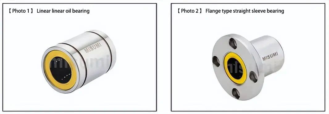
(1) Linear type and flanged type of linear bearings
(Photo 1) shows the linear type and (Photo 2) shows the flanged type.
The flanged linear bearing (Photo 2) has the following advantages:
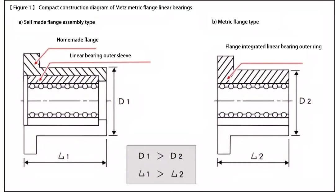
It has a more compact structure by adopting an integrated construction of linear bearing and flanged shaft sleeve ((Figure 1)).
Compared with a linear bearing combined with a separately produced flange, it has advantages such as low cost, short delivery time and stable quality.
(Figure 1) is a schematic diagram explaining the compact structure of flanged linear bearing. The mounting structure of the linear bearing with the flange and the shape of the shaft sleeve are very long, while the flanged linear bearing adopts an integrated structure, which is more compact. This compact design allows it to maintain load-bearing performance.
(2) Distinguish between linear types and flange types
Choose linear or flange bearing types according to the following criteria: Select linear bearing flange types if they are load-bearing.
Choose based on the surrounding space and building surfaces around the installation of linear bearings. See item (3) for installation methods and precautions regarding linear bearings.
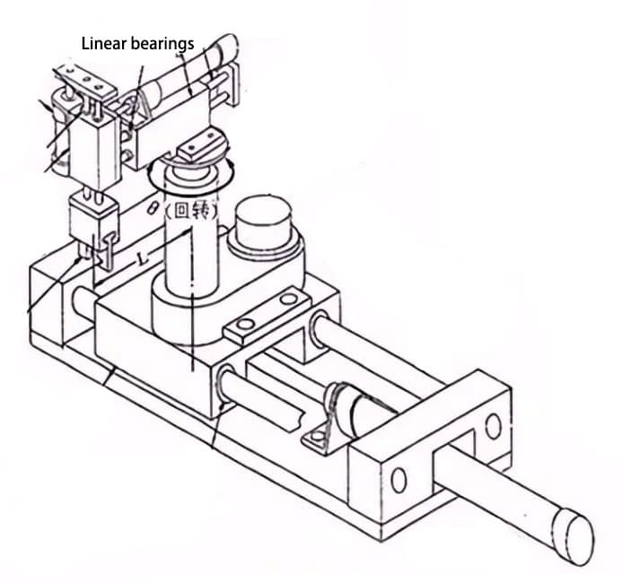
Linear bearings are divided into self-moving and shaft-fixed types for shaft rotation. Figure 2 illustrates the construction of an XYZ-θ driven platform with the axle as the guide axis. Bearings are classified accordingly.
- a) X axis: Linear bearings are self-locating and flange type.
- b) Y axis: Linear bearings are fixed (in the direction of the Θ axis) and allow movement in the direction of the A axis.
- c) Z axis: Linear bearings are fixed in the Z axis direction and allow movement in the Y axis direction.
For linear types, select snap ring or stop plate fastening methods based on desired fastening strength.
a) The moving part of the section in the X axis is subject to the inertial force of the weight of the moving part supported by the linear bearing. The linear bearing needs to be firmly fixed.
b) The linear bearing is fixed to the bearing seat, and due to the use of a cylinder to drive the shaft structure, the axial fixation of the linear bearing only supports the friction reaction force, therefore a compact design was adopted for the type linear. Additionally, the Y-axis linear bearings are adjusted in the opposite direction to the two axes relative to the driven platform rotation axis θ, allowing for high rigidity in relation to rotational torque.
c) If we consider it from the direction of the moving axis, it is equal to b) and will not support large forces.
(3) Installation methods and precautions for linear bearings.
(1) Installation methods for linear bearings
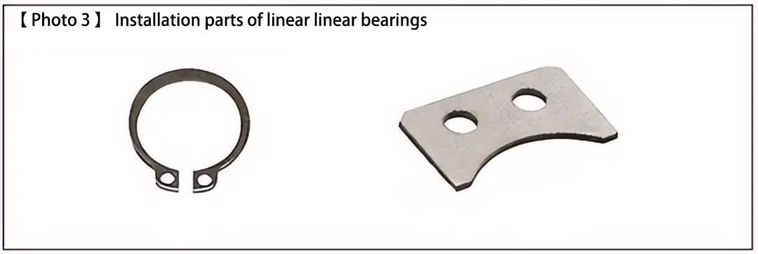
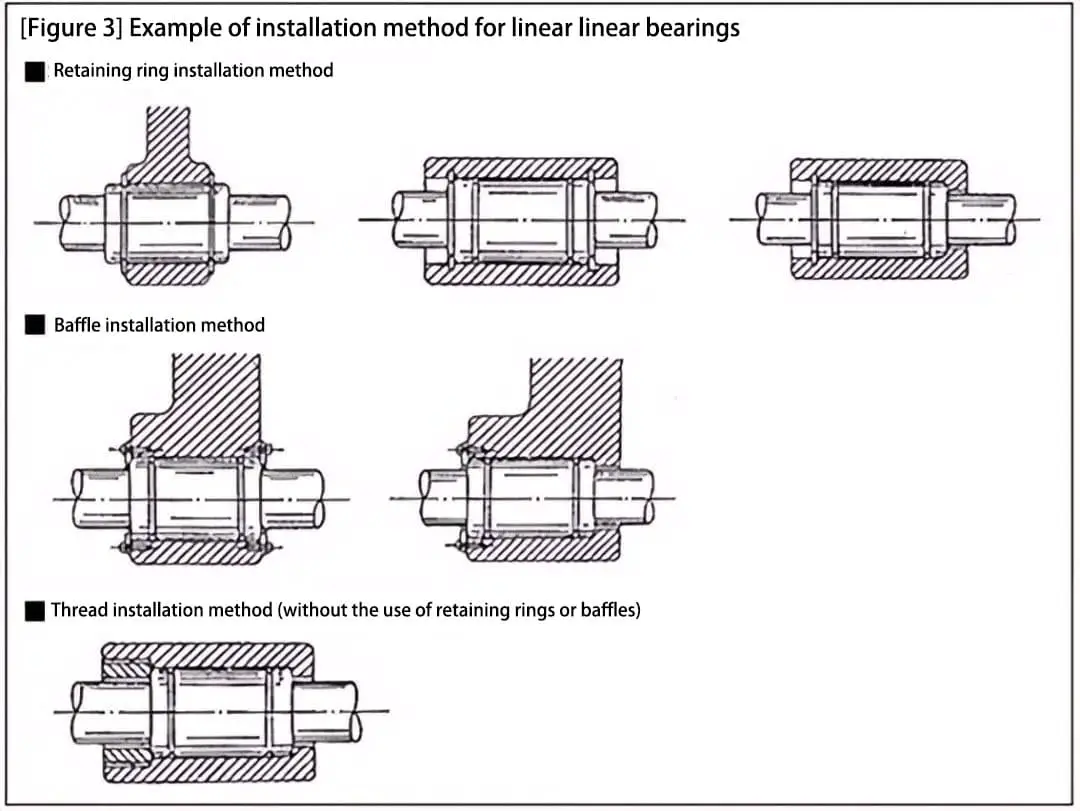
Linear bearings are typically installed using snap rings or stop plates (see (Photo 3) and (Figure 3)).
(2) Precautions for the installation angle of linear bearings
Due to differences in shaft diameter and type, as well as the number of rows of balls in the bearing, linear bearings generally have 4 to 6 rows of balls arranged at equal angles. When using linear bearings horizontally, avoid installing them with the rows of balls in the position directly above (as shown on the left side of (Figure 4)), as this can result in concentrated loads.
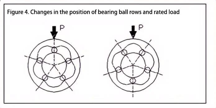
(Figure 4) shows a 5-row ball bearing, and the relationship of rated load values is shown below (right side ÷ left side). Therefore, installation should be done as close as possible to the installation angle shown in the diagram above.
- Nominal static load (right side ÷ left side) = 1.46
- Dynamic load rating (right side ÷ left side) = 1.19
3. Differentiation of single-coated, double-coated, extended and surface-treated bearings.
(1) Bearing length and guidance performance
Linear bearings can be divided into four types based on the length of the bearing:
- (1) single line
- (2) double lining
- (3) extended
- (4) Customer designed (using two types of single line).
The difference in bearing length directly affects the guidance performance as follows:
- a) Load capacity
- b) Guidance accuracy
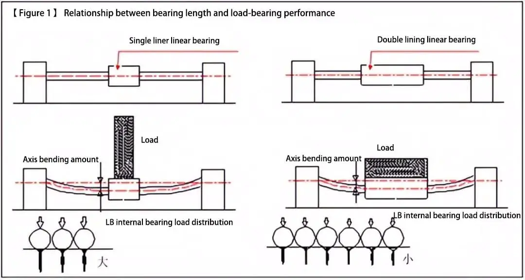
a) Relationship between support length and load-bearing capacity
The longer the bearing, the more support points there are and the lower the load required for each bearing contact point. This conclusion can be drawn from the real situation where the nominal load of the three types (1), (2) and (3) of linear bearings increases sequentially with their length.
Therefore, choosing a longer linear bearing length can improve the product's load capacity (=increased service life and reliability) ((Figure 1)).
b) Relationship between bearing length and guidance accuracy
The longer the bearing length, the greater the guidance accuracy.
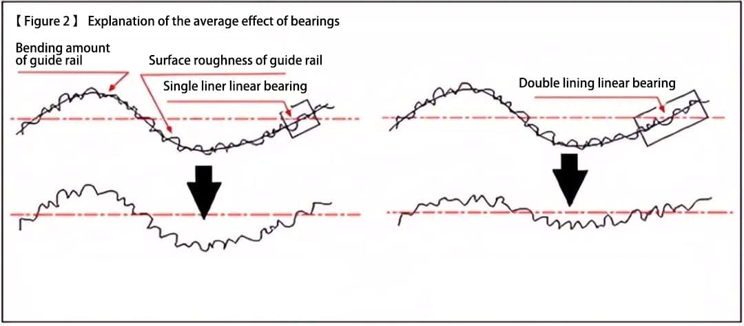
| 1) | By averaging the guide rail (axis) orientation error, product accuracy can be improved (see corresponding note for details) ((Figure 2)). |
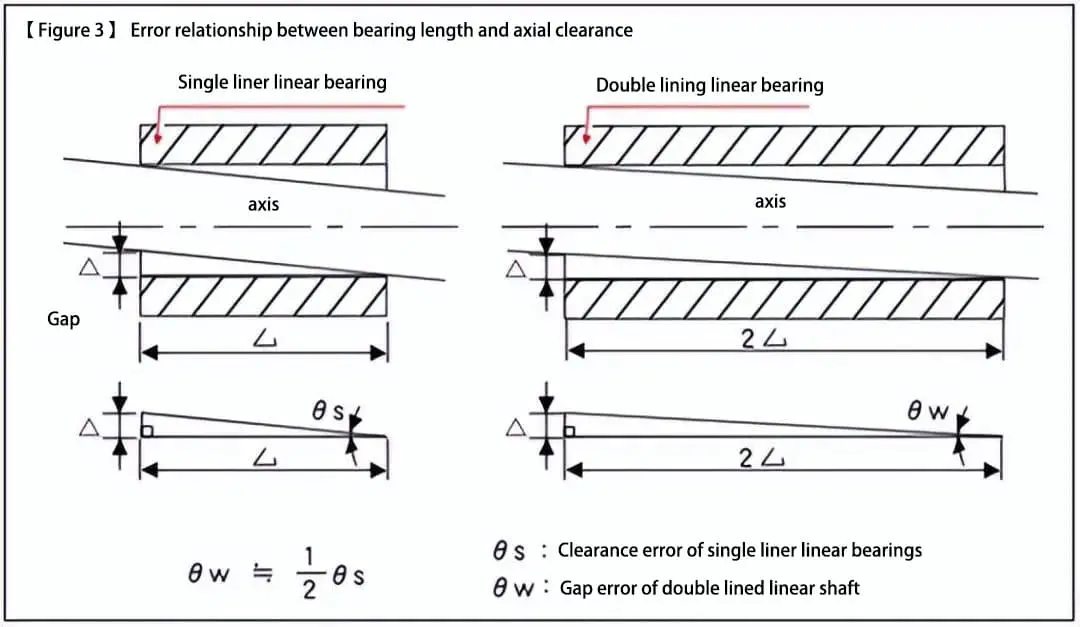
| two) | Product accuracy can be improved by reducing the clearance error between the guide rail (shaft) ((Figure 3)). |
The average effect of bearings: By increasing the length of the linear guide bearing, the number of bearing supports is increased and the error factors on the guide surface (surface roughness and bending deformation) can be calculated, with the effect of the error factor suppressed to less than half.
Therefore, by increasing the length of the bearing, the load-bearing capacity and guidance accuracy can be improved.
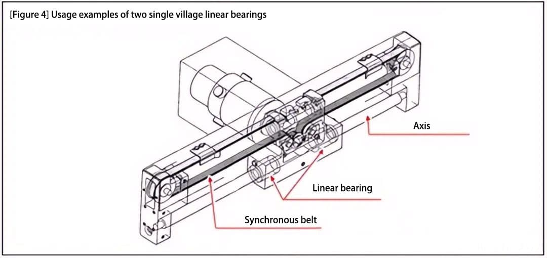
Therefore, type (4) (which uses a dedicated design with two types of single coating) of linear bearing is often used in high-precision working environments to a certain extent ((Figure 4)).
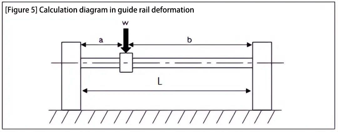
(2) Calculation of guide rail (axis) deformation ((Figure 5))
In a linear mechanism consisting of a linear bearing and a shaft, the shaft deformation can be calculated using the following equation:
δ = (W * a 3 * b 3 ) / (3 * E * I * L 3 )
where:
- a: Distance from the end point of the support to the loading position
- b: Distance from the end point of the support on the opposite side of a to the load position
- L: Distance between axle supports
- E: Young's Modulus
- I: Second moment of the cross-sectional area
- I = πd 4 /64 ≈ 0.05d 4
- d: Shaft diameter
- W: Load supported by the linear bearing (unit: N)
When a = b = L/2, δ = W * L3 / (9.6 * E * d4).
Therefore, if you want to reduce shaft deformation, you must adopt a design approach that increases the shaft diameter (4 times the effect) or shortens the distance between the shaft supports (3 times the effect).
(3) Characteristics and application examples of component materials and surface treatment
The constituent materials, surface treatments and application examples of linear bearings are presented in the following table:
| Outer ring material | Surface treatment | Retention material | Ball material | Application examples: |
| SUJ2 | – | Equivalent to Resin/SUS440C | SUJ2 | Sliding guide with general wear resistance requirement. |
| SUJ2 | Low temperature black chrome plating | Same as above. | Equivalent to SUS440C | Precision movement for reflection-free optical components in a dust-free environment. |
| SUJ2 | Ni-P Chemical | Same as above. | Same as above. | Chemical-resistant sliding parts in dust-free environments that require wear resistance. |
| Equivalent to SUS440 | – | Same as above. | Same as above. | Light load in a dust-free environment and equipment used in the food and medical areas. |
Comparative Characteristics of Surface Treatments.
| Outer ring material: | Surface treatment | Characteristics: |
| SUJ2 | – | SUJ2 is made of iron and can rust. |
| Same as above. | Low Temperature Black Chrome | Low coefficient of friction and good wear resistance Capable of forming a thin and uniform black coating that does not reflect light and has good heat absorption. |
| Same as above. | Ni-P chemical coating | Excellent resistance to chemical agents and corrosion, frequently used in clean rooms. Hard coating with a glossy, non-magnetic finish. |
4. Example of Application of Linear Bearings in Simple Automatic Equipment
The characteristics of linear bearings are described below:
- Simple, low-cost slewing bearings with average performance. (High cost-benefit ratio)
- Low coefficient of friction, facilitating drive selection. (Low-cost cylinder or mid-price engine type)
- By combining it with a synchronous belt, a silent and light driving construction design can be achieved.
- In the case of vertical directional guidance, the use of the center of gravity driving method allows for a simple and compact construction design.
The use and characteristics of linear bearings are explained below through an example of their application in simple automated equipment.
(1) Stepper motor and synchronous belt drive
The construction of the synchronous belt drive has advantages such as silence, lightness, low cost and no need for lubrication. For the X/Y/Z axis worktable situation, the usual design concept is to reduce the load on the lower X-axis motor by relieving the upper Y-axis.
Therefore, the Y axis is often constructed using a synchronous belt.
a) (Figure 1) shows a typical 3-axis X/Y/Z drive mechanism.
The X axis is made of linear guides, while the Y axis and Z axis are constructed of linear bearings. The drive system uses synchronous belts and ball screws.

b) (Photo 1) shows an example of applying the Y axis in an IC chip assembly device. The Y axis direction is converted into reciprocating motion by a synchronous belt.
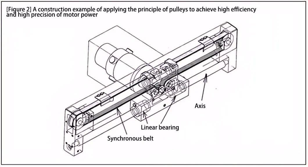
c) (Figure 2) shows an example of application of a single-axis robot with the following characteristics:
- Two linear bearings are used with a large span to improve bearing capacity and guidance accuracy.
- The design and structure of the synchronous belt and pulley use a rolling pulley principle ((Figure 3)) to achieve high motor power efficiency and high positioning accuracy.
- Synchronous belt transmission is light and silent.
- The synchronous belt and the shaft are arranged parallel up and down, and even with a single-axis structure, the relative rotation between the shaft and the linear bearing may be restricted.
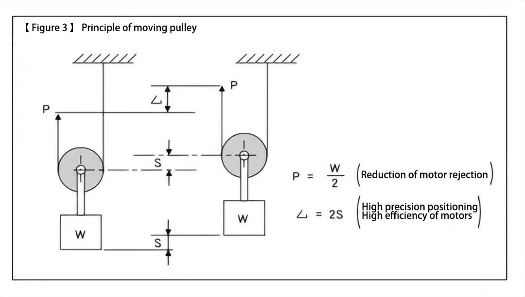
Movable pulley principle:
To lift the lifting object in Figure 3 by a distance S, the rope lock needs to be moved twice the height, but the force required is only half the weight of the lifting object, which can easily lift the lifting object.
2 times the moving distance
<1> Positioning accuracy that can improve the minimum resolution of motor rotation
<2> Reduce pulley recoil and idle error by half
<3> High speed (2x) motor rotation drive, resulting in high motor efficiency
1/2 times the load
<4> Can be driven by low power motor (no need for reduction gears, etc.)
(2) Stepper motor and ball screw
The ball screw drive method has the following characteristics: (1) it directly converts the rotary motion of the motor into linear motion, and (2) the ball screw pitch has the function of a reducer. The driving force transmission efficiency and engine efficiency are relatively high.
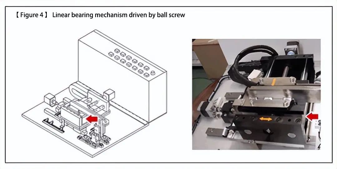
(Figure 4) is a drive mechanism in which the Y axis uses a linear bearing and a ball screw. This is generally applied to mechanisms that require unit power or that have positioning accuracy requirements.
Additional Information:
a) Characteristics of a stepper motor
Stepper motors have the characteristic of producing high torque in the low speed range (generally when starting and decelerating), making them suitable for short-distance movements and multi-point positioning control.
b) Necessary engine precision to achieve target positioning accuracy
Target positioning accuracy = ±0.01 (mm). By selecting a ball screw feed of 10 (mm/rev), the required precision (divisions) of the stepper motor can be calculated using the following formula.

(3) Cylinder drive
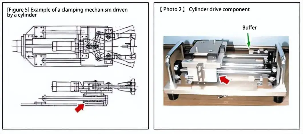
(Figure 5) is an example of a bearing used to drive a cylinder in a clamping mechanism, while (Photo 2) is an example of a cylinder drive mechanism that uses a magnetic coupling. Both use linear bearings (indicated by arrows) for guidance.
It is not possible to control the starting and stopping speed with cylinder drive, therefore a shock absorber must be used to reduce the impact when stopping (as shown in (Photo 2)).
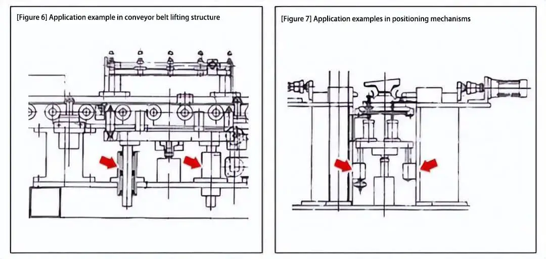
(4) Examples of vertical orientation
Vertical orientation can be achieved using linear bearings with flanges. No specific support structure is required to secure the linear bearing installation, which allows for a simple and compact structural design (in the case of sliding guides, where a vertical mounting substrate for the fixed guide rail must be installed).
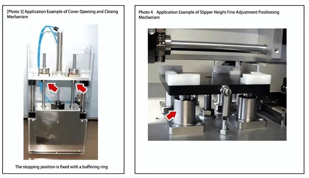
Similar to the structure in (Photo 4), the lifting guide (shown in (Figure 6)) and positioning mechanism (shown in (Figure 7)) at the bottom of the conveyor belt also use flanged linear bearings.