AUTOMATIC PNEUMATIC LATHE AND JACK
Holding and releasing the work is the most essential act in carrying out machining. These are commonly used in the machine shop.
1. To keep the work in proper position 2. To release the work quickly 3. To keep the work rigidly 4. To avoid vibration of the work during machining .There are many types of work holding devices such as machine vise, rotating vise, universal vise, pipe vise, T-Bolt 'U' clamps, gooseneck clamp, angle plate, jigs and fixtures, etc. In this project we are dealing with the pneumatic lathe used in drilling machines. Here loading and unloading are quick. The work can be carried out more rigidly.
There are three main types of work retention devices which are:
1. Mechanical type
2. Hydraulic type
3. Pneumatic type
In mechanical type , the screw shaft drives the movable jaw. One end is connected to the movable jaw and passes through a fixed nut. When we turn one end of the screw shank, it rotates the nut and in turn moves the movable jaw. Here the rotary motion is converted into reciprocating motion.
In hydraulic one end of the piston rod is connected to the movable jaw and the piston slides in the cylinder. Here the hydraulic fluid drives the movement of the piston; this, in turn, actuates the movable jaw. Here the main movement is just a reciprocal movement. The pneumatic type is the same as the hydraulic type. Here, instead of hydraulic fluid, air is used.
WORK OPERATION
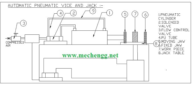 Automatic pneumatic lathe and jack working diagram
Starting initially with air packs, their function is to compress air from a low inlet pressure (usually atmospheric) to a higher pressure level. This is achieved by reducing the air volume.
Air compressors are generally positive displacement units and are of the reciprocating piston type or rotary screw or rotary vane type. The air compressor used here is a two-stage compressor unit, typically small in size. It also consists of a compressed air tank, electric rotor and pulley drive, pressure controls and instruments for quick connection and use. The pressure exceeds the design pressure of the receiver, a release value provided that releases excess air and thus prevents any hazard that may occur.
The compressed air goes to the solenoid valve through the flow control valve. The flow control valve is used to control the amount of air flow into the cylinder. This flow is manually adjusted by the nap fixed above the flow control valve. Then this air goes to the 5/2 solenoid valve. The 5/2 solenoid valve has one inlet port, two outlet ports and two exhaust ports. The 5/2 solenoid valve is controlled by the electronic timing control unit. The on/off speed of the solenoid valve is controlled by this timing control unit. The 2 output ports are connected to an actuator (cylinder). The pneumatic drive is a double-acting, single-rod cylinder. The cylinder output is coupled to another purpose. The piston end has an air horn effect to prevent sudden thrusts at the ends.
WORKING PRINCIPLES
- Compressed air from the compressor reaches the solenoid valve. The solenoid valve changes the flow direction according to the signals from the timing device.
- Compressed air passes through the 5/2-1 solenoid valve and is admitted to the front end of the cylinder block. The air pushes the piston to clamp the workpiece. At the end of the stroke, air from the solenoid valve reaches the rear end of the cylinder block. The pressure remains the same but the area is smaller due to the presence of the piston rod. This puts greater pressure on the piston, pushing it at a faster rate, thus allowing for a faster return stroke.
- Compressed air passes through the 5/2-2 solenoid valve and is admitted to the front end of the cylinder block. The air pushes the piston, so the workpiece is lifted. At the end of the lifting stroke, air from the solenoid valve reaches the rear end of the cylinder block.
- The pressure remains the same but the area is smaller due to the presence of the piston rod. This puts greater pressure on the piston, pushing it at a faster rate, thus allowing for a faster return stroke.
- The piston stroke length can be changed by making a suitable adjustment to the timer
BENEFITS:
1. Machine downtime is reduced.
2. When compared with lathes, it consumes less time to clamp and loosen the work.
3. Reduces manual labor
4. Hence the production rate is higher
5. There is no backlash in this mechanism.
DISADVANTAGES:
1. Higher initial cost.
2. It may be an air leak choice
3. Cylinder stroke length is constant
FORMS:
1. To hold work rigidly during machining.
2. For quick fixing and unfastening of work.
SUGGESTION:
This is not only intended for drilling machine lathes, using a large capacity cylinder and lathe, it can be used to clamp and unclamp work in most machining processes.