In the mechanical engineering and instrument making industries, interchangeability of parts and components means that a batch of parts or components of the same specification can be installed on the machine without selection or additional repair (e.g. bench repair) to meet the requirements of specified performance.
To ensure the interchangeability of parts in mechanical production, the dimensions of production parts must be within the desired tolerance limits. This should establish a uniform standard for the shape, size, accuracy and performance of a type of part. Similar products should also have appropriate size gradation to reduce the product series. This is product standardization. This is how the concept of specified technical tolerances and adjustments emerged.
What is technical tolerance?
Suppose a metal bar 100 mm long is being processed. Even if all bars have the same shape, the manufacturing accuracy of bars cannot be achieved exactly as 100.00 mm for all bars due to the size and orientation of the bars. Although design and manufacturing sites have worked to reduce such variations, they still cannot be controlled to zero.

This size and shape deviation basically fluctuates up and down, with the target value being the focus. Therefore, the upper allowable value and the lower allowable value of the upper allowable value are determined relative to the target size based on the use of the metal rod. The difference between these two values (allowed range) is called “tolerance”.
In short, tolerance is the deviation of parts in the processing process. Due to the effects of deviation, the accuracy of measuring equipment must be guaranteed. It is the amount of deviation allowed for a given dimension to achieve proper functioning. Dimensions of parts within the desired tolerance range are qualified. Technical tolerances include dimensional tolerance, shape tolerance and position tolerance.
Dimensional tolerance
Dimensional tolerance is the allowable deviation of a size. This is the basis of technical tolerance. The maximum value allowed is called the maximum dimension. The minimum value is called the minimum dimension.
Tolerance means the value of the algebraic difference between the maximum upper limit size and the minimum upper limit size, as well as the value of the algebraic difference between the upper deviation and the lower deviation.
Tolerance is a numerical value without plus or minus signs and cannot be zero. With a constant basic size, the smaller the dimensional tolerance, the greater the dimensional accuracy. The specified tolerance indicates manufacturing accuracy requirements and reflects the degree of difficulty of machining.
Shape Tolerance
(1) Righteousness
Straightness is the condition in which the actual shape of a straight element in a part maintains an ideal straight line. It is also known as degree of straightness. The straightness tolerance is the maximum deviation that the actual line will allow from the ideal line. That is, in the specified drawing, the actual allowable line processing tolerance is limited by the deviation tolerance range.
(2) Flatness

Flatness is the representation of the actual shape of the flat elements of the part to maintain the ideal plane. This is commonly called the flatness level. The flatness tolerance is the maximum deviation that the actual surface will allow from the plane. That is, in the drawing, the actual tolerance of surface processing is limited by the tolerance range of permissible changes.
(3) Circularity
Circularity is the condition in which the actual shape of the elements of a part is the same distance from its center. The degree of roundness, as it is often called. The circularity tolerance is the maximum allowable deviation of the actual circle from the ideal circle in the same section. That is, the deviation range specified in the drawing limits the machining tolerance of the actual circle.
(4) Cylindricity
Cylindricity refers to the point on the contour of the cylindrical surface of the part, keeping its axes equidistant from each other. The cylindricity tolerance is the maximum deviation that the actual cylinder allows from the ideal cylinder surface. It is specified on the drawing and is used to limit the allowable range of actual cylindrical machining tolerance.
(5) One-line profile
The purpose of a line profile is to represent the curve of any shape in a given plane of the part and maintain its ideal shape. The profile tolerance of a line is the allowable deviation from the actual contour of a non-circular curve. That is, it is specified in the drawing to limit the range of deviation allowed by the actual curve processing tolerance.
(6) Profile of a surface
A surface profile is a surface of any shape on the part to maintain its ideal shape. The profile tolerance of a surface is the allowable deviation of the actual contour of a non-circular surface from the ideal contour. It is specified in the drawing and serves to limit the actual machining area of the surface.
Position tolerance
Position tolerance refers to the total amount of change allowed by the position of each element relative to the reference point. It is another important technical tolerance parameter.
(1) Directional tolerance
Directional tolerance refers to the total deviation in direction that the reference allows in relation to each element. Such tolerance includes parallelism, perpendicularity and angularity.
(2) Site tolerance
Positional tolerance is the total range of deviations in a position that allows real elements to be correlated with the reference. This type of tolerance includes concentricity, symmetry and position.
(3) Deviation tolerance
A deviation tolerance is a specified tolerance value based on a specific test method. Concentricity tolerance can be divided into concentricity and total concentricity. The tolerance of the above shapes and positions is collectively called geometric dimensioning and tolerance (GD&T).
General tolerance
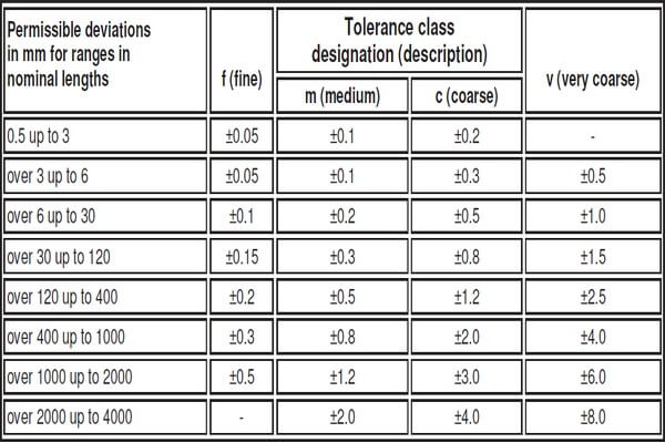
In technical drawings, these unspecified dimensions, in addition to the tolerance for certain dimensions and characteristics, are often required to meet certain standards. Take our commonly used international tolerance standard DIN ISO 2768 as an example: the general dimensional tolerance is m, the shape tolerance is K. And the marking method is ISO 2768-mK. Below is a table of linear dimensional tolerance levels for your reference.
Basic rules
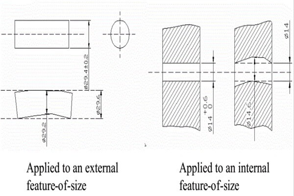
Rule #1: Envelope Rule
This is a requirement for dimensional tolerance and GD&T to be related to each other. The envelope rule dimension member's actual tolerance must equal the entity's maximum limit. i.e. its external function dimension does not exceed the entity's maximum dimension. And its subdimension does not exceed the minimum dimension of the entity.
Rule #2 Independence Rule
The principle of independence is that each size and shape specified in the drawing is independent of its location and must meet its own requirements. This is the basic principle that the relationship between dimensional tolerance and shape tolerance must follow.
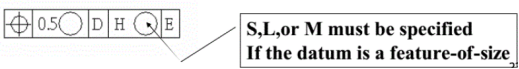
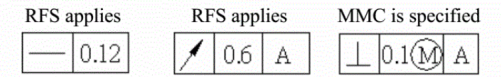
Rule #3: Position Rule Tolerance
For position tolerance, when dimension features are reference points, S, L, or M must be specified in the feature tolerance frame.
Rule #4: Different from the Position Tolerance Rule
For everything except a positional tolerance, the RFS applies to the tolerance, the datum reference, or both if no modifier is specified. MMC should be specified in the resource control board when appropriate and desired.
Suitable for
In mechanical assemblies, the relationship between a hole of the same basic size and the shaft tolerance zone is called fit. Since the actual hole and shaft sizes are different after assembly, play or interference may occur. In hole-to-shaft fit, the algebraic difference of hole size minus shaft size is a gap if it is positive and an excess if it is negative.
Coordination is divided into three categories depending on differences in gaps or interruptions:
Slack adjustment
The hole tolerance range is greater than the shaft tolerance range and each pair of holes connected to the shaft results in a loose fit (including a minimum clearance of 0).
Pressure adjustment
The hole tolerance range is below the shaft tolerance range and any pair of holes that match the shaft will provide an interference fit (including a minimum clearance of 0).
Overfitting
The hole tolerance overlaps the shaft tolerance so that a pair of holes fits the shaft loosely or press fit.
The essence of selecting the appropriate tolerance level is to adequately resolve the contradiction between the operational requirements of machine components and the machining process and cost. The principle in selecting the tolerance level is to agree on a tolerance level lower than the maximum possible, provided that the application requirements of the parts are met.
Requirements for precision machining must be coordinated with production possibilities. In other words, low-cost process technologies, assembly technology and existing equipment must be used. However, if necessary, strategies should be adopted to improve the accuracy of equipment and improve the method of ensuring the accuracy of goods.
It is very important to select the acceptable tolerance range for the appropriate size. In many cases, this determines the operational performance, service life and reliability of the appropriate components. And at the same time, it affects parts manufacturing costs and production efficiency.