1. Dimensional tolerance of flat stamping parts and formed stamping parts
(1) Dimensional tolerance table of flat stamped parts
Unit: mm
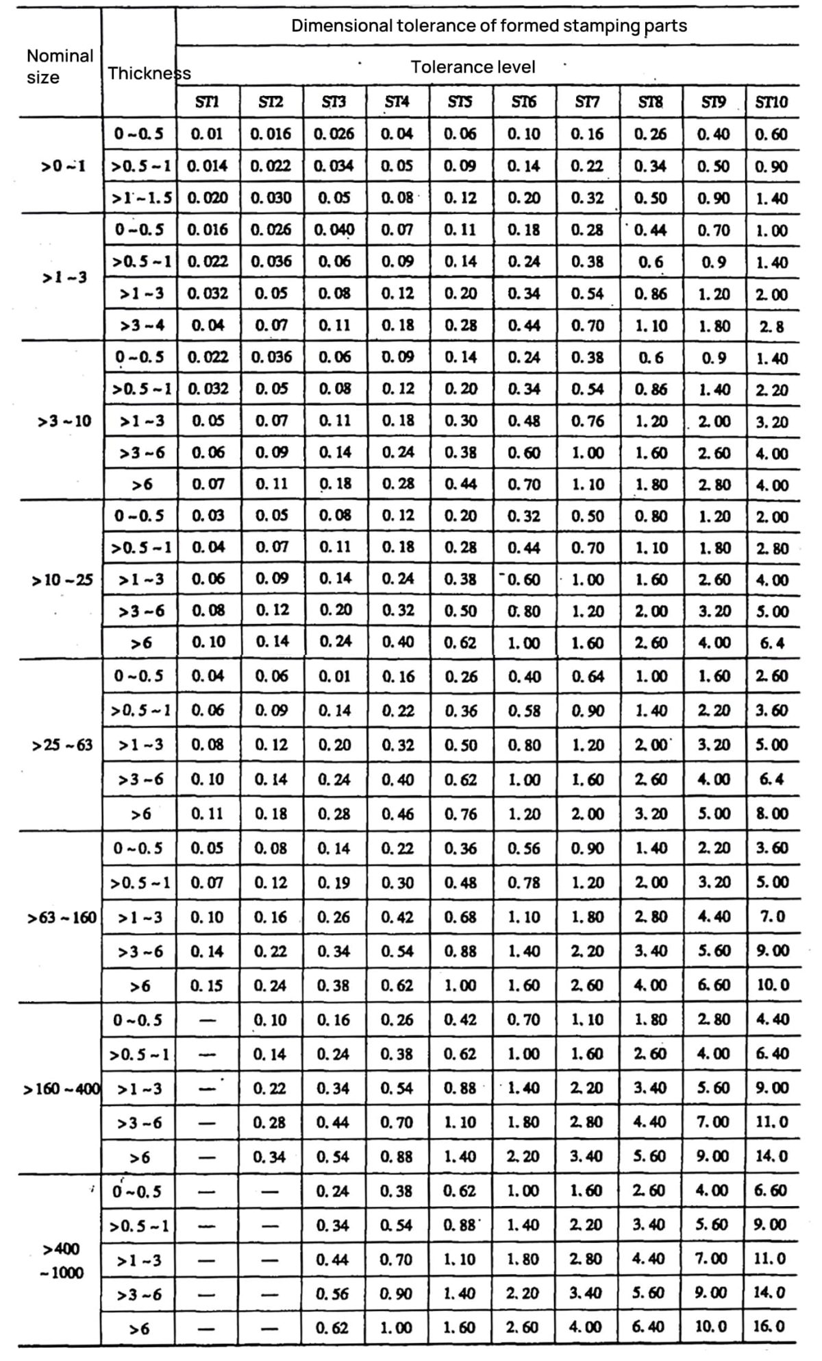
(2) Dimensional Tolerance of Formed Stamped Parts
Unit: mm
Observation:
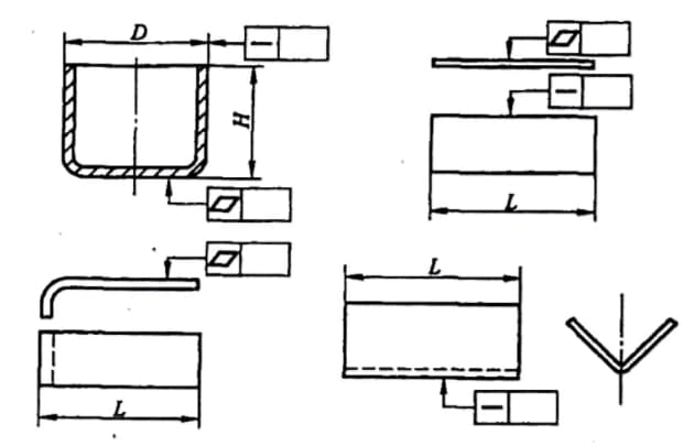
- Flat stamps are stamps formed by flat punching. Formed stampings are stamps made by bending, deep drawing and other forming methods.
- The flat blank dimensional tolerance applies to flat blanks and also to dimensions formed by punching operations on formed blanks.
- The limit deviations of the dimensions of the formed flat and stamped stampings are selected in accordance with the following rules:
1) For hole dimensions (internal shape), the limit deviation is obtained from the tolerance values given in the table, with “+” being used as the upper limit deviation and the lower limit deviation is 0.
2) For shaft dimensions (external shape), the limit deviation is obtained from the tolerance values given in the table, with “-” being used as the lower limit deviation and the upper limit deviation is 0.
3) For hole center distance, hole edge distance and length, height and non-tolerated dimensions formed by bending, deep drawing and other forming methods, the limiting deviation is half of the tolerance value given in the table, with “± ” used as the deviations of the upper and lower limits.
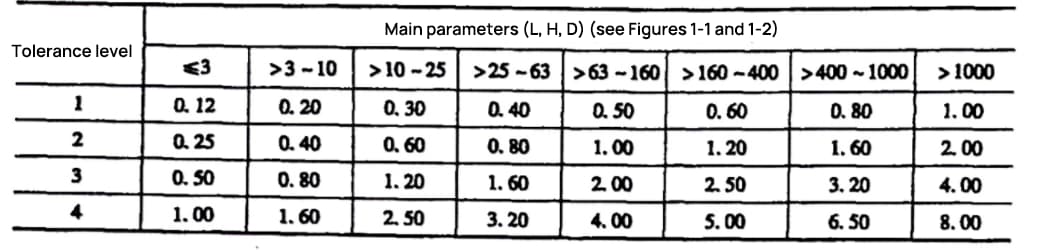
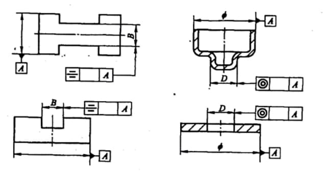
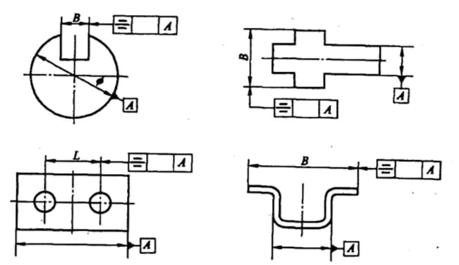
2. Unnoted coaxiality and symmetry tolerances are
Coaxiality, symmetry and primary parameters (L, H, D) are indicated in the figure below.
Unit: mm
3. Limit the deviation of dimensions from unobserved tolerances (drilling, forming)
Unit: mm
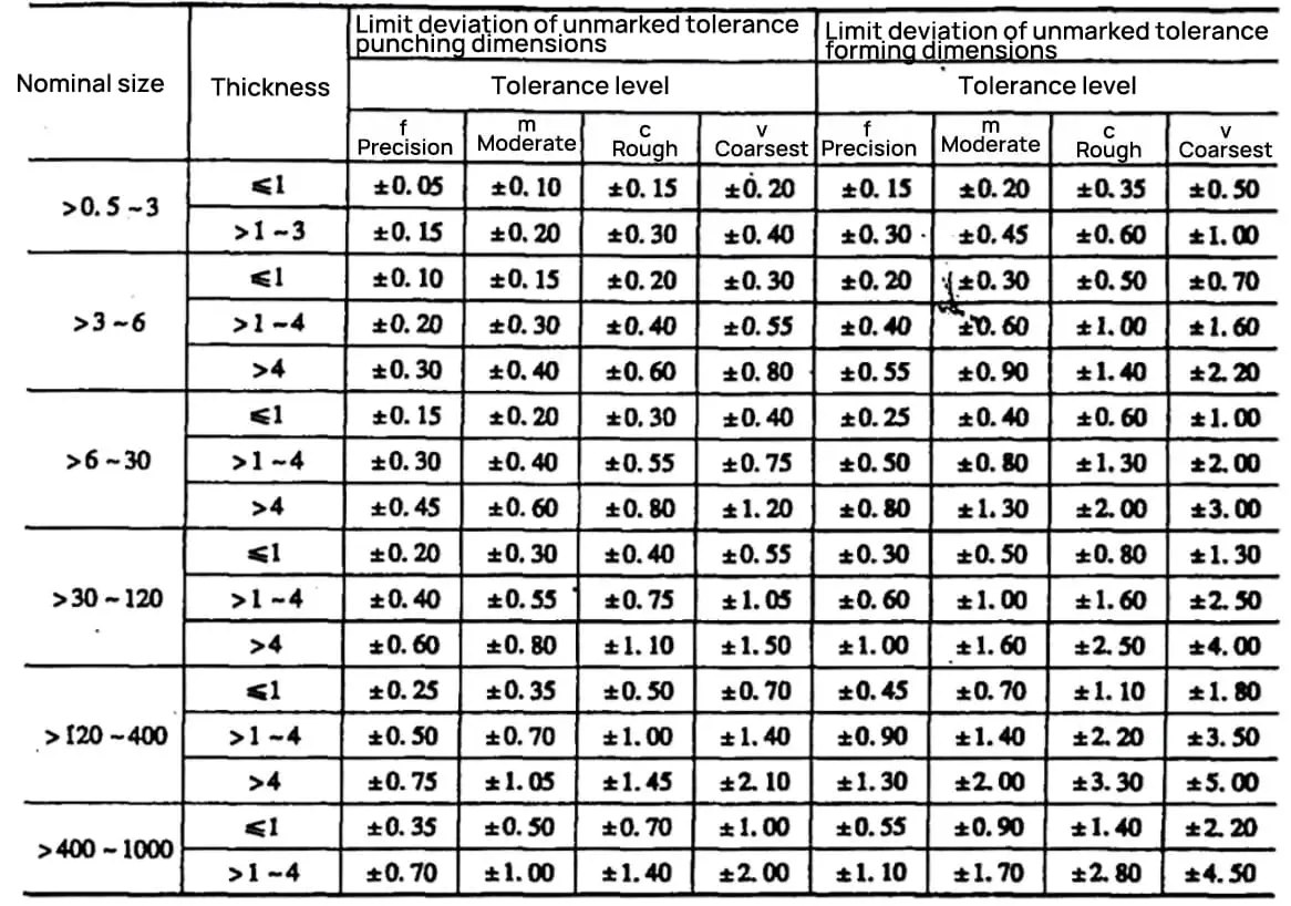
Observation:
- Tolerances must be marked for dimensions of 0.5 mm and below.
- This table is applicable to non-tolerated dimensions of distance from hole center, distance from hole edge, and lengths and heights formed by bending, deep drawing, and other forming methods.
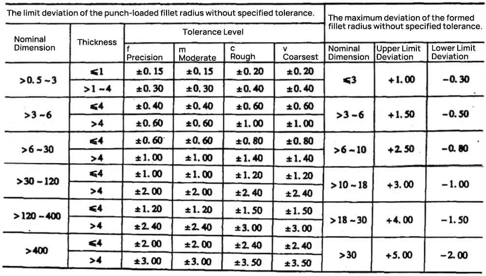
4. Limit deviation from the unobserved tolerance (drilling, forming) of the fillet radius
Unit: mm
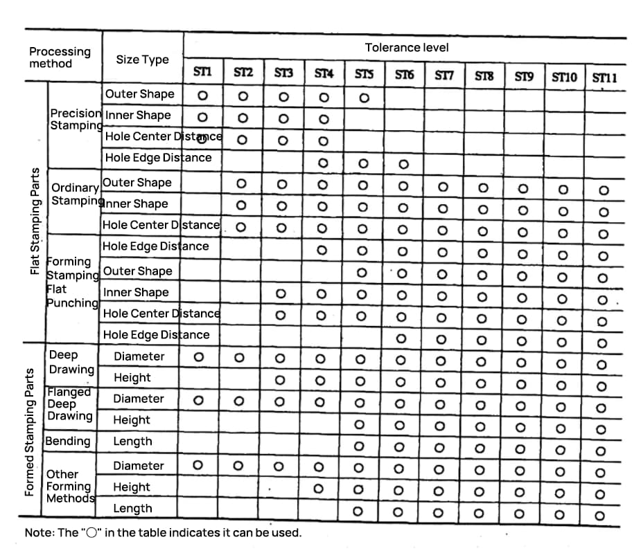
5. Selection of Dimensional Tolerance Level
6. Angular Tolerance
Unit: mm
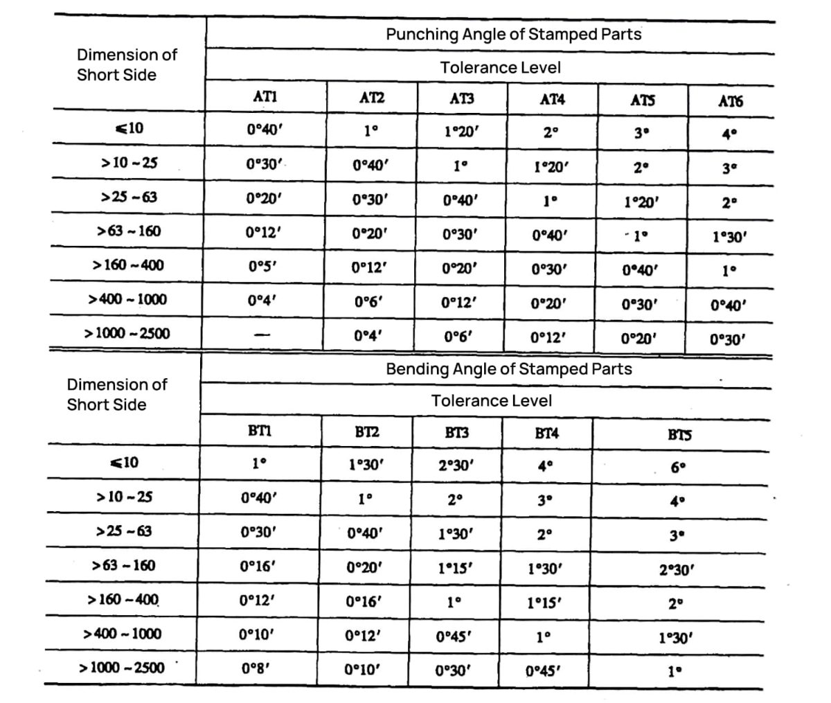
Observation:
- The shear angle of a stamped part refers to the angle created by the stamping or forming process on the flat portion of the stamped component.
- The bend angle of a stamped part refers to the angle created by the bending process in the stamped component.
- The difference in the maximum values of the shear angle and the bending angle of the stamped part must be selected according to the following criteria:
1) A one-way bypass is chosen based on usage requirements.
2) For undeclared tolerance of angular limit deviations, half of the tolerance value given in the table, indicated with a “±” sign, is considered as the upper and lower limit deviations.
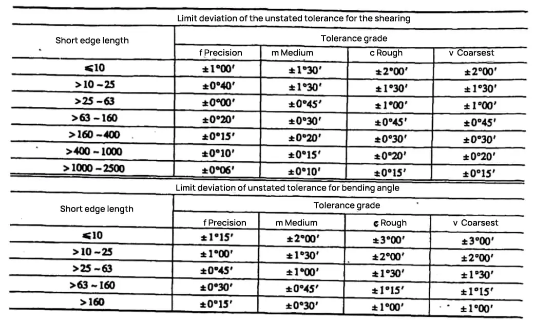
7. Limit deviation of angles from unnoted tolerances (drilling, cutting, bending)
Unit: mm
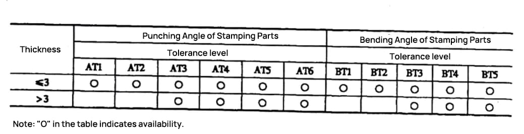
8. Selection of angular tolerance level
Unit: mm
9. Unnoted flatness and straightness tolerances
The primary parameters (L, H, D) of flatness and straightness are indicated as shown in Figures 1-3.
Unit: mm