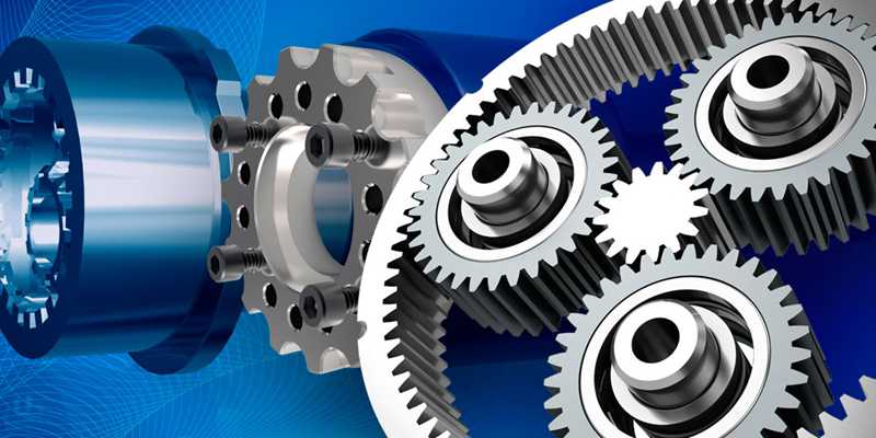
Gears are essential to the proper and efficient operation of many machines, including many CNC machines. Its importance in these machines comes from its ability to perfectly transfer movement, force and torque between different parts.
There are several important details about gears, including their different types, classes, and how to maximize their effect. We will go into all these details in this article and also the best way to use gears in the manufacturing industry.
Understand the different gear parameters
The parameters of a gear are merely technical properties of the gear. These parameters apply to different gear parts and must be considered by industrial engineers.

number of teeth : Teeth are the serrated surfaces outside the circumference of the gear. For teeth, there can only be an integer as the number of teeth. Furthermore, the number of gear teeth determines the gear ratio, which in turn affects the behavior of the gear.
Total depth : This is the distance between the outermost part of the tooth and the bottom of the tooth.
Part circle : Gears are generally circular and the pitch circle is the parameter that determines the size of the gear. To form a gear, the meshed gears must have tangential pitch circles. This parameter is the most important of all other circumference-related gear parameters, and all others are defined according to the pitch circle. Furthermore, the pitch circle divides the tooth into tooth height and tooth depth, that is, the top and bottom of the tooth.
Root circle : This is the internal diameter of the gear, important for outlining the bottom of the tooth.
Outer circle : This is the outer diameter of the gear and defines the top of the tooth.
Pitch circle diameter : This is simply the diameter of the gear and is found by measuring the diameter of the pitch circle. The diameter of the pitch circle is important for estimating the ideal distance between two gears.
Circular split : This is the distance between two adjacent teeth on a gear. It is determined by marking a piece on one tooth and marking the same piece on the next tooth and measuring the distance between these two parts. The pitch provides valuable information about the number of gear teeth.
modulo : This parameter refers to the circle pitch and is found by dividing the circle pitch value by 3.142 (Pi). In analyses, the gear modulus is often preferred to the circular pitch.
Diametric division : This parameter relates the diameter of the pitch circle to the number of gear teeth. Pitch diameter is important in determining whether two gears mesh because only gears with the same value for this parameter mesh.
Circle Thickness : Simply put, this is a measurement of the thickness of an individual tooth on the gear.
How mechanical gears work
When you use a mechanical transmission, you see two gears meshing and transmitting speed and motion. But what happens behind the scenes?

First of all, you should know that gears are attached to components called shafts. The rotation of the gears occurs along the axis. The two gears that mesh are the driving and driven gears. The driving gear is responsible for the initial rotation, while the driven gear is the gear that causes the final rotation due to the action of the driving gear. Each rotation of the drive gear results in a rotation of the driven gear.
With all gears there is a transfer of motion between the driving and driven gears. However, for some gears the transfer of motion may result in a change in the direction of rotation, while for other gears it may result in movement. The design of the two gears is decisive for rotation or a change in movement.
In machines where speed and torque must be influenced by the mesh of the teeth, the gear pairs can be made of different sizes.
Gear Classification
There are several ways to classify gears. The two most common are the following:
Classification based on tooth shape
- Involve
- Cycloid
- Trochoid
Classification based on axis configuration
Parallel : The waves are parallel and in the same plane. The driving and driving wheels move in opposite directions to each other, and the motion transmission efficiency is generally high. Examples of gears based on this configuration include helical gears and racks.
Overlaps : The axes intersect in the same plane and the transmission efficiency is usually high, as with the parallel arrangement of the axes. Examples of gears based on this arrangement are bevel gears.
Non-parallel and non-intersecting : Waves that do not fall into any of the previously mentioned classes, that is, the waves are not parallel and are not in the same plane. The transmission efficiency is quite low. Examples of gears based on this configuration are helical gears.
Different types of gears
There are different types of gears depending on their properties and design features. In addition to understanding how gears work, it is important for mechanical engineers to understand the different types and their specific characteristics to obtain the best possible results. These gears are described below.
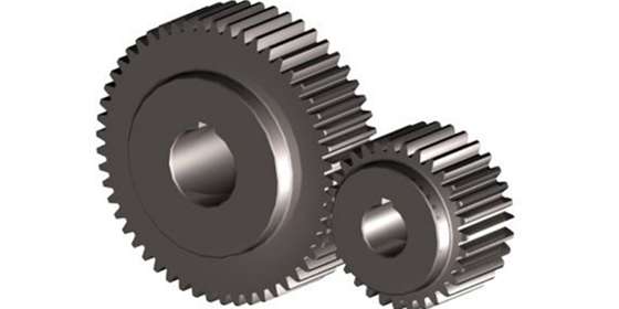
1. Spur gear
Spur gears are the most common types of gears in machines due to their simple design. Spur gears belong to the class of gears in which the tooth runs parallel to the shaft. Because these gears are constructed in parallel, the efficiency of movement and power transmission is generally high.
A special feature of spur gears is that they do not transmit any load in the axial direction. Furthermore, due to their design, spur gears are ideal gears for processes that do not require high speed.
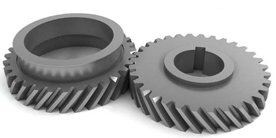
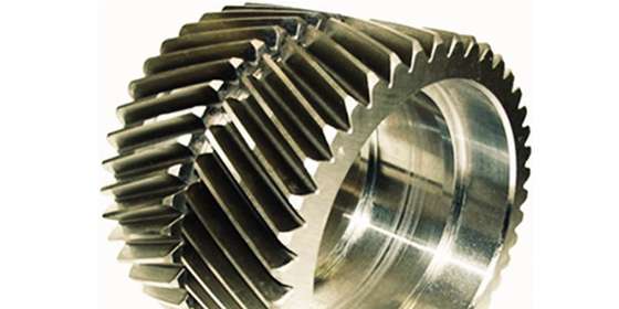
2. Helical gear
Helical gears are so called because they have a spiral shape that resembles helical springs. Just like spur gears, helical gears are often used in manufacturing and machinery.
However, unlike spur gears, which have teeth arranged parallel to the shaft, the teeth of helical gears are arranged at an angle to the shaft. There are also more teeth involved in transmitting motion and speed, which means helical gears can support a greater load.
Here too, helical gears transfer the load in the axial direction, which creates a thrust force and requires bearings. Helical gears are ideal for operations that require high speeds. There are different variants of helical gears, namely the following:
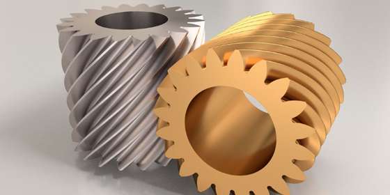
2.1 Single or double helical gear
Depending on whether the gears have teeth on one or both spirals, helical gears can be divided into two divisions. If there are teeth on only one spiral, it is a single-cut gear. The side (left or right) of the teeth does not matter as long as only one side has teeth.
However, gears are called double helix if they have teeth on both sides. With double helical gears, there is a gap between the two surfaces. Of the two subtypes, double helical teeth are more efficient and transmit movement more smoothly because the teeth overlap more.
2.2 Screw gears
Helical gears are a pair of helical gears of the same name with a rotation angle of 45 degrees. They have a similar design to many fasteners. These gearboxes typically work with gears that are neither parallel nor crossed. Unlike traditional helical gears, helical gears have only one tooth as a contact point, compromising their ability to transport high powers and loads.
3. Herringbone gear
This type of helical gear is similar to the double helical gear, except that the herringbone gear is shorter and there is no clearance between the two surfaces. Although herringbone gears are suitable for operations involving high levels of vibration and shock, they are expensive and difficult to manufacture, which is why they are not widely used in industry.
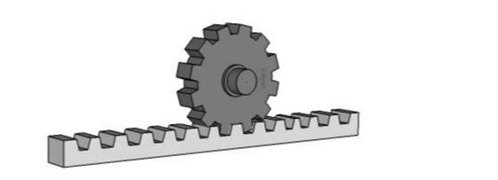
4. Rack and pinion gear
This type of gear has similarly sized teeth, equidistant from each other along a linear rod called a rack. Additionally, the rack has a pair of circular gears, called pinions, that mesh with the rack. The engagement between the pinion and the rack converts the rotary movement into linear movement. This type of gear is mainly used in the automotive industry to produce steering systems.
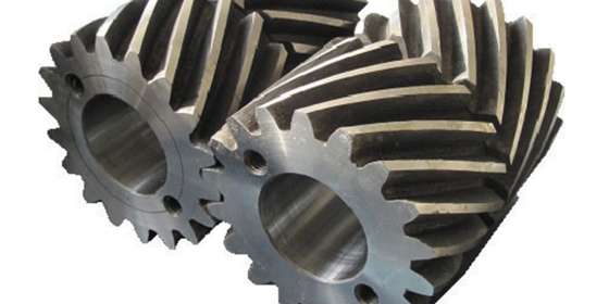
5. Bevel gear
A bevel gear is a cone-shaped gear with teeth around the cone that is used to transmit power between cross shafts. Waves can cross each other perpendicularly or at a certain angle. This type of gearbox is not commonly used in industry because it is relatively expensive. However, the gearbox is used in the production of mixers and crushers.
There are different types of bevel gears highlighted below:
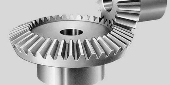
5.1 Spur bevel gears
This subtype of bevel gear is the most common in many industries, mainly due to its simple construction. Although the pitch of the wheel is conical, the teeth are vertical.
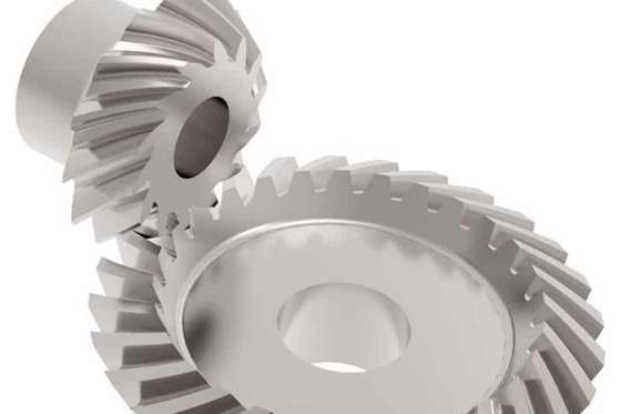
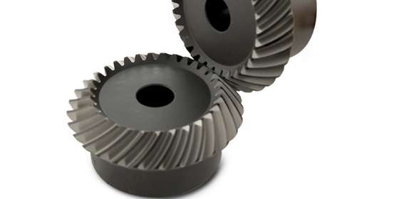
5.2 Spiral bevel gear
This subtype of bevel gear features a curvature in the tooth line, which corresponds to excellent contact points between the gear teeth. The result is a stronger gear with a smoother transmission. However, they are very expensive.
5.3 Angular gear
If a bevel gear has a gear ratio of one, it is called an angle gear. This is an important feature considering that other gearboxes of this type can have a gear ratio of up to 400:1. Angle gears are the best bevel gears for operations that require efficient transmission at high speeds.
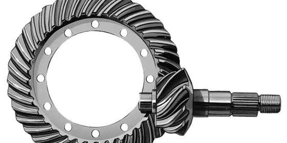
5.4 Hypoid gears
There is a striking similarity between spiral bevel gears and hypoid bevel gears. The main difference is whether the waves intersect or not. If this is the case, the bevel gear is called a spiral bevel gear; otherwise, the gear is a hypoid bevel gear.
Other types of bevel gears include:
- Bevel helical gears
- Angular bevel gears
- crown gears
- Zerol bevel gears
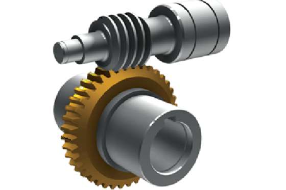
6. Worm gear
This type of gearbox consists of two important components: the worm and the worm wheel, which are simply the shaft and corresponding gear. The shafts of this gear have a thread cut like a drill and do not intersect.
Power transmission is generally very smooth and quiet because there is little friction between the hard worm wheel and the soft worm wheel. However, this type of transmission is not the most efficient. Helical gears are mainly used in agricultural machinery.
7. Internal gear
This type of gear has teeth on the internal cones. To transmit motion, an external gear is paired with an internal gear, with both gears rotating in the same direction. As the number of teeth on internal and external gears is usually different, some problems may arise when using this type of gear. However, the gear is useful in shaft couplings.
Considerations and tips for gears in mechanical engineering projects
There are different types of equipment that belong to different classes. Choosing the right equipment is crucial to the success of the operation. However, due to the variety of equipment available, it can be difficult to determine which equipment is right. Fortunately, there are some considerations and tips that can help you choose the right equipment. That includes:
1. Budget
All manufacturing companies want the best and most efficient machines for their operations. This can sometimes result in the need to customize gearboxes based on technical drawings and recommendations to meet your needs.
Unfortunately, this adjustment isn't cheap. In addition to customization, some gears are very expensive and difficult to manufacture. It is important to consider the budget before choosing a gearbox to manufacture.
2. Design Patterns
There is no single standard for designing and manufacturing gears. Instead, there are different technical specifications, standards and tolerances to which gears can be manufactured. For companies that require the equipment, it is important to consider the special standards of the equipment.
If these companies do not receive a specification that meets their needs, they may have to move to another region to obtain the correct equipment. Regions with different standards are the United States, Japan and Germany.
3. Space limitations
The space available in the gear design is an important factor that determines the gear choice for a manufacturer. Generally, gears are located in the middle of the shafts. However, in some cases, manufacturing requirements may require the gears to be further from center. In this case, the equipment needs to undergo some other changes to maintain its effectiveness and efficiency. One of these changes is an adjustment of the tooth profile and thickness.
Alternatively, manufacturers can use gears that make better use of space. The most commonly used gear for this is the internal gear.
4. Transfer needs
Mechanical transmissions are generally used to transmit motion and torque between different parts of a machine. Different machines have different transmission requirements and needs. Some machines only require a change in motion, some machines only require a change in torque, while some machines require a change in both motion and torque.
Depending on the manufacturer's requirements for its operation, a suitable gearbox can be selected and then the type and design of the gearbox can be adjusted.
5. Terms of Service
The conditions under which mechanical gears operate can affect their performance and service life. Operating conditions can be divided into operating and environmental conditions. For the first, the following considerations are important: gearbox weight, friction, noise, vibration and load.
On the other hand, the following aspects must be taken into consideration with regard to environmental conditions: temperature, cleanliness and humidity. Therefore, environmental and operating conditions affect the gear construction material, surface treatment and lubricants used.
Gear types applications
Gears are used in different industries for different operations. Some of the most common uses are:
- Vehicle steering
- Airplanes
- water systems
- power plants
- Packaging equipment
- Agricultural tools
A diagram for each type of gear application
| Types of equipment | Equipment names | Typical products |
| spur | spur gear | Clocks Trains Plane Clothes washing machines power plants |
| Spiral-shaped | Simple helical gear Double helical teeth herringbone gear Screw Gear |
Auto Industry Clocks Irrigation systems home appliances |
| chamfer | Spur bevel gear Spiral bevel gear Angular gear bevel gear Hypoid gear Zero gear crown gear |
bombs Trains Plane power plants |
| worm | helical gear | Elevators Auto Industry |
| Rack and pinion gear | Rack and pinion | Scale Trains |
Concluding
Gears are mechanical devices that help transfer power and torque between the different components of a machine. There are different classes and types of gears with different applications.
Manufacturers need to understand how gearboxes work, their different classes and how to select the right type of gearbox taking into consideration relevant aspects to maximize productivity and efficiency.
Common questions
What is the difference between gears and sprockets?
The first difference between the two is that sprockets don't fit together perfectly like gears. Another difference is that sprockets transmit torque only along the parallel axis, while gears do so in either direction. In terms of application, gears are the preferred devices for short-term torque transmission, while sprockets can transmit torque over longer distances.
What materials are gears made of?
There are different types of materials for making gears, both metallic and non-metallic. These materials include steel, cast iron, nylon, fiber, plastic, etc. The material to be used generally depends on the requirements of the gears.
What treatment methods are used for gears?
Before the gears can be used, some treatment techniques are usually used. Typical ones include grinding, a type of surface processing common in CNC materials, and heat treatment. Surface finishing by grinding aims for smooth operation and low noise of the gear, while various heat techniques are used to affect the strength and durability of the gear.