The true art of engineering is evident in complex mechanical assemblies. Take a look inside a wristwatch. The perfect harmony in which all the little components work together is simply fascinating. This is an excellent example of technical adjustments, which is the topic of this discussion.
In this article we will talk about the different types of adjustments, their patterns, applications and some common techniques for making them. Let's start!
What is an engineering adjustment?
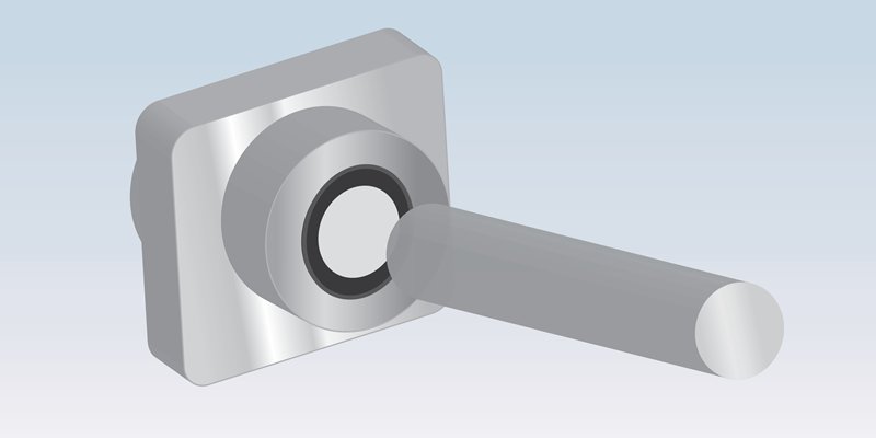
Engineered fits are a type of mechanical assembly in which two mating parts are joined together permanently or temporarily. The word “fit” characterizes the mechanical distance or extent of physical contact between corresponding components.
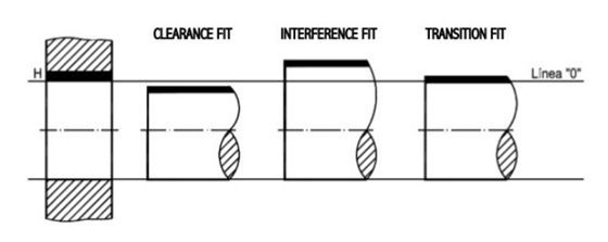
If the parts fit together perfectly and the connection can withstand loads, it is an interference fit. A transition fit, on the other hand, characterizes a connection that absorbs enough force to maintain contact, but cannot withstand high loads. The third category, loose fit, has a small space between mating components that allows free rotation or sliding between them.
Adjustment basis: hole and shaft system
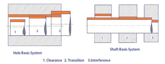
The shaft hole and base system is a popular standard for engineered fits. There are two variants: perforated base or corrugated base systems. In both, the base component has fixed dimensions while the other component is sized to achieve fit. For example, in the shaft base system, the shaft diameter is fixed and the hole diameter is adjusted.
Of the two, the hole base system is by far the more popular as it makes it more convenient to control the diameter of shafts compared to holes.
However, the wave base system is not completely ignored. If shaft sizing is not possible, such as a shaft rotating rapidly after mass balancing, the hole size will be changed to achieve the fit.
Types of adjustments
As briefly mentioned, there are three main categories of technical adjustments. Each one has a different mechanical contact and a different task. In this section we will go into more detail about these types of adjustments and their subcategories.
1. Pressure adjustment
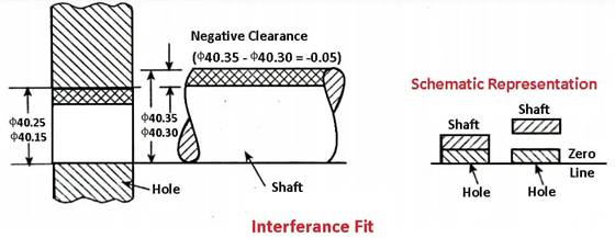
Press fit is a type of engineered fit in which the mating surfaces are held firmly together by high frictional forces. Therefore, press fit is also called friction fit.
The tightness of the pressure adjustments results from its negative play. This means that the corresponding surfaces are pressed against each other. In other words: The contact surfaces deform inward under contact pressure. For example, with a hole and shaft system, in a press fit the hole is actually smaller than the shaft. The shaft is pressed forcefully into the hole using a hydraulic press or hammers (another name for interference fit).
Another common method for creating pressure fits is shrinking. In this technique, one of the parts is cooled or heated so that it contracts or expands to such an extent that the negative gap briefly changes to positive gap. After the pieces are positioned together, temperatures return to normal. The resulting thermal contraction/expansion creates a tight interference fit.
In general, the clearance for an interference fit is -0.001 mm to -0.042 mm. Now let's take a look at the interference tuning subcategories:
Pressure fit : A lighter version of the pressure fitting with minimal negative clearance for medium resistance fittings.
Driving capacity : Medium size joint capable of carrying loads and requires pressure and cold/hot force for assembly.
Press fit : Press fits are the most stable type of engineered fit. They require cold/hot pressing and are almost always permanent. Its assembly requires careful tolerances and positioning to avoid breaking parts.
2. Slack adjustment
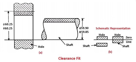
A loose fit has positive play. This means that there is a small gap between the contact surfaces. This means that the parts also have some play, but this is insignificant and often not visible to the naked eye.
Due to this clearance, freely fitting parts have a certain degree of freedom (of movement). For example, screws and frames in swivel joints have a loose fit, allowing both components to move independently while remaining locked in place.
The usual clearance range for these technical adjustments is between +0.025 mm and +0.089 mm. Below is an overview of the types of clearance adjustments:
Easy Run : The game is set at the upper limit of the range specified above. Loose fit parts may rotate/slide freely and have noticeable play.
Freewheeling : Similar to a loose connection. Parts can move at high speeds and the connection can accommodate thermal expansion. However, positional accuracy is low due to significant backlash.
Tight run : Tight fits have slightly better positioning accuracy and allow parts to move even at high temperatures and speeds.
Sliding systems : Sliding joints are high-precision technical adjustments. The distance is kept to a minimum to limit all degrees of freedom except the sliding direction.
Location : Position adjustments are high-precision adjustments to precisely position mating parts. The play is very small and requires lubrication to allow for smooth movement.

3. Transient adjustment
The transition adjustment is a compromise between the other two technical adjustments. Depending on the application, mating parts may have a small oversize or gap.
With a negative interference, such as an interference fit, the pressure and load capacity are not as high. In a game, like a pass game, the game is not that big.
Typically, a transition fit is useful for accurately positioning parts during assembly operations. It limits their relative movements and at the same time avoids extreme mechanical stress.
The mechanical clearance for transition adjustments is between +0.023 mm and -0.018 mm. Additionally, there are two common types of transition adjustments:
Similar fit : A very light technical fit with almost no looseness/excess. Generally, human strength with a hammer is sufficient to achieve the adjustment.
Tight fit : A little tighter than a similar fit needed to achieve a press.
Technical adjustments: the big picture
The information in the previous section may be too extensive to absorb all at once. To understand them better, let's zoom out a little and try to get an overview of the technical adjustments. A good way to do this is to discuss general technical standards for tuning types.
The two most common standards for technical adjustments are ISO 286 and ANSI B4.1. Both standards provide comprehensive information on tolerance ranges for different types of fits. Reference tables of these standards can be found in all production workshops, which highlights their importance in the industry.
As the ISO standard is the better known of the two, the following table focuses on it.
| Fit type | hole base | shaft base | Adjust | Forms |
| Slack adjustment | H11/c11 | C11/h11 | Loose fit for running | Pivot points, corroded and dusty parts, parts subject to thermal fluctuations |
| H9/d9 | D9/h9 | Free running adjustment | Cylinder-piston units, slow-rotating parts | |
| H8/f7 | F8/h7 | Comfortable fit for running | Machine tool spindles, spindle bearings, sliding joints | |
| H7/g6 | G7/h6 | Sliding adjustment | Sliding wheels, clutch discs, hydraulic pistons | |
| H7/h6 | H7/h6 | Position clearance adjustment | Machine tool guides, roller tracks | |
| Transient adjustment | H7/k6 | R7/h6 | Location transition adjustment | Wheels, brake discs, gears/pulleys on axles |
| H7/n6 | N7/h6 | Location transition adjustment | Motor armature windings, gears | |
| Pressure adjustment | H7/S.6 | P7/h6 | Local interference adjustment | Hubs, couplings, bushings for bearings |
| H7/s6 | S7/h6 | Medium steering adjustment | Permanent gear/pulley assemblies, bearing assembly | |
| H7/u6 | U7/h6 | Force action | Flange mounting, gears, shafts |
How can dimensional tolerances for adjustments be achieved?
From the above discussion, it is clear that dimensional tolerance is a critical factor for accurate engineering adjustments. However, producing the right parts within the required dimensional tolerances requires a lot of skill.
Generally, tolerance limits are indicated on technical drawings using appropriate GD&T symbols. GD&T establishes acceptable limits for the amount and nature of geometric deviations from actual geometry. Therefore, the manufacturer must produce the parts within these specified limits.
Manufacturers can achieve this goal using numerous techniques. That includes:
Precision CNC Machining : CNC machines have remarkable accuracies of up to +/- 0.001mm. With the right tools and fixtures, machinists can produce precise parts for technical adjustments.
Grinding : Grinding is the preferred method for ultra-precision manufacturing due to its impressive manufacturing accuracy of +/- 0.25 microns. For critical applications such as press fit, tolerances of this magnitude are common.
Rubbing : It is a special application for making holes. Since holes are a very common fastener in engineered fits, friction is worth mentioning in this list. Because it is a precise method that only removes a small amount of material, it is useful for placing holes within the tight dimensional tolerances required for mechanical adjustments.
Concluding
Technical adjustments are essential for the manufacturing industry. Without them we wouldn't have created any product! The three types of fits: press fit, transition fit and clearance fit, all play an essential role in various products such as shafts (gears, pulleys and bearings), machine tool guides, couplings, etc. this topic as a technical professional.

Common questions
What are the fits and tolerances?
Mechanical/engineering fits or fits are a type of mechanical connection in which two parts are joined together with some distance between their contact surfaces. The distance can be positive or negative depending on the type of mechanical adjustment. Tolerances are the dimensional limits within which these parts must be manufactured to obtain the correct type of fit.
How do I choose the right solution for my application?
The choice of technical adjustment depends on several factors. The range of motion or load capacity of the connection is the first consideration. Other important factors are the quality and strength of the components to be assembled, the geometry of the part, manufacturing options and manufacturing costs.
How do you calculate technical fit tolerance?
Technical fit tolerances can be selected using guidelines from well-known technical standards such as ISO or ASME. Detailed information on technical dimensions and tolerances can be found for each fit type and hole/shaft size.