
1. Understand waterjet technology
Waterjet technology is a new technology developed in the last 20 years and its applications are increasingly widespread. It has been applied in sectors such as coal, machinery, petroleum, metallurgy, aviation, construction, water conservancy and light industry, mainly for cutting, grinding and cleaning materials.
Especially in recent years, with the rapid development of high technology, laser beams, electron beams, plasma and water jets have become new cutting tools.
Among them, laser beam, electron beam and plasma belong to thermal cutting processing, while water jet is the only cold processing method. In cutting, crushing and surface pre-processing of many materials, water jet has its unique superiority.
Waterjet development can be divided into four stages:
Exploration and experimental phase: In the early 1960s, low-pressure water jet mining was mainly studied.
Equipment development stage: From the early 1960s to the early 1970s, mainly high-pressure pumps, boosters and high-pressure accessories were developed, while waterjet technology was promoted.
Industrial application stage: From the early 1970s to the early 1980s, a large number of waterjet mining machines, cutting machines and cleaning machines appeared successively.
Rapid development stage: From the early 1980s to the present, research on water jet technology has deepened further, and new types of jets such as abrasive jet, cavitation jet and self-excitation vibration jet have been developed. developed quickly. Many products were commercialized.
The four stages of waterjet cutting development.
- The fourth stage: Rapid development stage.
- The third phase: industrial application phase
- The second stage: Equipment development stage.
- The first stage: Experimental exploration stage.
Abrasive waterjet concept:
Abrasive waterjet is a special processing method that uses water as the medium, obtains tremendous energy through a high-pressure generating device, adds abrasives to the high-pressure waterjet through a feeding and mixing device, and forms a two-phase mixture of liquid and solid.
It relies on the high-speed impact and erosion of the high-pressure, abrasive water jet to achieve material removal.
Abrasive water jet processing principle:
Abrasive water jet processing is based on the principle of hydraulic pressure, which uses a high-pressure generator or high-pressure pump to pressurize water at ultra-high pressure.
The mechanical performance of the electric motor is converted into pressure energy, and the water with tremendous pressure energy is then transformed into kinetic energy through a small hole nozzle. This forms a high-velocity water jet and creates a certain degree of vacuum in the mixing chamber.
Under the action of its own weight and pressure difference, the abrasive is sucked into the mixing chamber and violently agitated, diffused and mixed with the water jet, forming a high-speed abrasive water jet that impacts the workpiece in a extremely high speed through the abrasive nozzle.
After the abrasive water jet impacts the workpiece, a concentrated, high-speed local stress field is produced in the material, which changes rapidly, leading to erosion, shearing, and ultimately material failure and removal.
In the abrasive water jet processing process, the main function is played by abrasive particles, and the water jet acts as a conveyor to accelerate the abrasive particles.
Compared with pure waterjet, abrasive waterjet has higher kinetic energy due to the larger mass and higher hardness of abrasive particles, resulting in stronger processing effects.
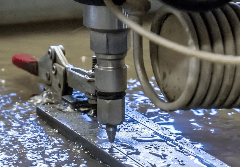
Abrasive water jet device
The abrasive water jet device includes a water supply system, a pressurization system, a high pressure waterway system, an abrasive supply system, a cutting head device, a receiving device, a drive and a control system as shown in the figure below.
The role of the water supply system is to soften the water quality, reduce the corrosion of the high-pressure watercourse caused by the water quality, and improve the service life of the alternative seal in the high-pressure system.
The main component of the pressurization system is the pressure intensifier, which generally uses hydraulic reciprocity.
The pressure ratio of the intensifier is generally selected as 10:1 or 20:1, and the intensifier outlet water pressure can be adjusted by changing the oil pressure of the inlet hydraulic system, which can increase the water pressure to 100-400MPa, and up to 690MPa and 700MPa. The high pressure waterway system connects the pressurization system and the cutting head device.
In order to transport high-pressure water and meet the requirements of fast and flexible movement of the cutting head, high-pressure water piping generally uses ultra-high pressure resistant flexible stainless steel pipes and is composed of multiple joints. rotating tubes.
The abrasive supply system includes a hopper, an abrasive flow valve and a transport tube. The pure water jet cutting head includes a high-pressure water switch valve and a jewel nozzle. The abrasive waterjet cutting head also includes a mixing chamber and a mixing nozzle that mixes the waterjet with the abrasive.
The mixing nozzle requires high wear resistance and is generally made of carbide. The receiving device is placed below the workpiece to collect the remaining abrasive jet and has functions such as energy absorption, noise reduction, splash prevention and safety.
The actuation mechanism and control system control the cutting head movement trajectory control device, and the control methods include manual, motorized, NC and CNC.

Abrasive:
It is generally divided into three categories: mineral-based, metal-based and artificial.
Selection principle:
(1) Good cutting effect;
(2) Low price and sufficient supply.
Common abrasives include:
Tab.1.2 Various commonly used abrasives
| Abrasive name | Mesh count | Particle size (um) | Purpose |
| Grenade | 40 | 420 | Rough machining |
| Grenade | 50 | 297 | The cutting speed is slightly faster than 80 mesh, but the surface is slightly rough |
| Grenade | 80 | 178 | Most commonly used general purpose |
| Grenade | 120 | 124 | Produce a smooth surface |
| quartz sand | Ideal abrasive for sandblasting and rust removal for steel surfaces | ||
| alumina | Polishing Supplies |
Nozzle:
It consists of a water jet nozzle, a mixing chamber and an abrasive jet nozzle.
Classification:
(1) According to the number of water jets: single-jet nozzle, multi-jet nozzle
(2) According to the abrasive input method: abrasive side feeding nozzle, abrasive medium feeding nozzle, tangential abrasive feeding nozzle.
1. Single jet abrasive side feed nozzle

- mixing chamber
- Abrasive jet nozzle
- water jet nozzle
Advantages: Simple structure, good concentration and jet stability.
Disadvantages: Poor mixing effect between abrasive and water.
2. Single jet abrasive tangential feed nozzle

- water jet nozzle
- Abrasive jet nozzle
The abrasive and the water jet are fully mixed, while reducing the mutual collision between the abrasives, thus improving the cutting ability of the abrasive jet.
3. Multi-jet abrasive intermediate feed nozzle

It is mainly used for abrasive blast cleaning or rust removal.
4. Abrasive jet nozzle with straightening tube

- Nozzle body
- Abrasive Entry
- water jet nozzle
- Nozzle base
- Stamp
- Lock-nut
- Straightening Pipe
It has a simple structure and is easy to operate. It is widely used in the abrasive jet cutting industry.
Classification of abrasive waterjet processing technology:
According to the mixing method of abrasive and water, it can be classified into two types:
- Front hybrid abrasive water jet.
- Rear hybrid abrasive water jet.
Front hybrid abrasive waterjet:
The abrasive and water are evenly mixed into an abrasive slurry in the high-pressure pipeline, and then the jet formed by the abrasive nozzle is called the front mixed abrasive jet. This mixing effect is good, requiring low pressure, but the device is complex and the nozzle wears a lot.
Rear Hybrid Abrasive Waterjet:
Adding abrasives to the water jet after it is formed is called back-mixing abrasive water jet. The mixing effect is a little worse, requiring high pressure, but the nozzle wears less. The theoretical research and application technology of back-mixing abrasive waterjet are relatively mature and have been widely used in many industrial sectors.
Classification of Abrasive Waterjet Machining Technology.
- Submerged abrasive water jet.
- Non-submerged abrasive water jet.
Submerged water jet refers to the jet that is in the water from the outlet to the workpiece, which has the characteristics of rapid jet diffusion, uniform velocity distribution and dynamic pressure.
Non-submerged water jet means that the jet is in the natural state of air from the outlet to the workpiece. Compared with the submerged jet, it has greater range and longer core length, but the velocity distribution is not uniform.
2. Cutting mechanism and cutting law of abrasive water jet.
Abrasive waterjet cutting mechanism:
When cutting a target material with an abrasive water jet at a given jet travel speed, a portion of the water jet shoots toward the target material at a constant speed, while another portion weakens its cutting force as it penetrates further. deep into the material.
As a result, the cut surface appears to bend in the opposite direction of the jet crossing, as shown in Figure a below. The angle between the axis of the bent cutting surface and the axis of the original jet gradually increases from where the jet enters the target material, and the jet increasingly deviates along the opposite direction of traversal.
However, due to the large inertia of the abrasive particles themselves, they do not deflect with the water jet conveyor, leading to the separation of the abrasive particles from the water jet and the erosion of the local concentration of the abrasive particles.
The greater the acceleration of the abrasive particles, the greater the refracted angle at separation and the more severe the concentration erosion. Erosion due to local concentration of abrasive particles causes a significant increase in the amount of grinding along the cutting surface, forming a step on the cutting surface.
Therefore, during the erosion that forms the step, the deflection angle of the water flow above the step increases continuously, the deflection of the water jet from the cutting surface increases, and the amount of grinding below the step decreases until the upper step flattens. make it perpendicular to the original direction of the jet, as shown in Figure b below.
As the jet passage continues, the cutting surface returns to smooth cutting and grinding, as shown in Figure c below. From this point, the cutting cycle begins again with the transition from smooth cutting and grinding to creep erosion and grinding.
During this process, the entire cutting surface continues to transform into a path gap, and as the deflection of the abrasive water jet approaches an arc, it forms a cutting cross section with a wave-like gap along it. the direction of the jet crossing.

- a- The cutting surface may be bent due to the smooth cutting and grinding process.
- b- The formation phase of the cutting surface is mainly due to erosion, deformation and grinding.
- c- The cutting surface is transformed back into a smooth cutting and grinding surface along the feed direction.
Mathematical model of machining with abrasive waterjet:
M. Hashish, based on the solid particle erosion theory of Finnie and Bitter, and a series of visualization experiments, proposes that the abrasive waterjet material removal process consists of two regions: cutting wear and cutting wear. deformation, as shown in the figure below.
In the cutting wear region, i.e., before the cutting depth reaches hC, the abrasive particles impact the material at a small angle, and the material is removed in microcutting mode. When the cutting depth reaches hC, the impact speed of abrasive particles on the material decreases and the material removal mode changes.
The abrasive particles impact the material at a large angle and the material is removed in a creep wear mode.
Based on this, M. Hashish obtains the mathematical models for the cutting depth in the cutting wear region and the cutting depth in the creep wear region:


where
- h c is the cutting depth (mm) for cutting wear mode;
- h d is the cutting depth (mm) for the deformation wear mode;
- C k is the characteristic speed (m/s);
- d j is the jet diameter (mm);
- m is the mass flow rate of abrasive particles (g/s);
- V e is the critical speed (m/s) of the abrasive particles;
- Vó is the initial velocity (m/s) of the abrasive particles;
- ρ p is the density (g/cm3) of the abrasive particles;
- u is the displacement speed (mm/s) of the nozzle;
- C f is the friction coefficient;
- σ is the shear stress (MPa).
This model includes almost all parameters involved in abrasive waterjet machining. However, some parameters such as Vo and Ve need to be determined experimentally. Therefore, the results obtained by different operators may vary.
Factors affecting abrasive waterjet cutting performance:
As abrasive waterjet cutting is a very complex process, there are many parameters that can affect its cutting performance.
These parameters include dynamic parameters (water nozzle diameter, water pressure), abrasive parameters (abrasive material, size, flow rate), abrasive nozzle parameters (abrasive nozzle diameter, length, material), cutting parameters (cutting speed , standoff distance, impact angle, number of cuts), workpiece parameters (hardness) and so on. However, the process parameters that are easy to control mainly include water pressure, abrasive parameters, cutting speed and standoff distance.
The main indicators for evaluating cutting performance include depth of cut, shape of the cut (width of the top and bottom of the cut and taper of the cut) and surface quality (roughness and waviness).
Abrasive waterjet cutting laws:
(1) The cutting depth increases with increasing water pressure, abrasive hardness and number of cuts, while it decreases with increasing cutting speed. There is an ideal value relationship between cutting depth, standoff distance, abrasive supply and abrasive particle size. As the depth of cut increases, the peak height and deflection angle of the flutes in the cutting section gradually increase, while the occurrence frequency of the flutes decreases.
(2) The cutting width has an ideal value relationship with the cutting speed, and the ideal cutting speed is about 1/5 of the maximum cutting speed. In a single cut, the cutting speed is determined by the material properties, thickness and quality requirements of the section. When the transverse speed is constant, the greater the pressure, the smoother the cutting surface; when the surface roughness is the same, the greater the pressure, the greater the transverse speed.
(3) With increasing jet pressure or decreasing cutting speed, the quality of the cutting section improves significantly. Compared with brittle materials, the cutting section of plastic materials is smoother, and its morphology is more affected by jet pressure and cutting speed.
(4) The speed of the cutting area of the abrasive water jet decreases with the increase in the fracture energy value of the material, increases with the increase in pressure, and decreases with the increase in the standoff distance. There is an ideal value relationship between the speed of the cutting area and the abrasive supply. When the transverse speed and material thickness are constant, there is an ideal distance value that results in the deepest depth of cut. As the standoff distance increases, the groove width gradually increases. When the pressure is constant, the lower the transverse speed, the greater the cutting depth.
3. Current research status of abrasive waterjet machining technology.
Abrasive cutting with water jet.
M. Hashish is one of the first researchers to study abrasive waterjet machining. Through experiments with abrasive waterjet cutting, he discovered that it can be used to cut felt, ceramics, metals, glass and sintered graphite composites without delamination.
Furthermore, he observed that there is no thermal stress or deformation stress in the cutting zone. He also discussed the effect of different cutting parameters on material processing performance and material removal rate, and highlighted that optimizing cutting parameters will greatly improve cutting performance.
Since then, a large amount of domestic and foreign research and applications of abrasive waterjet machining have mainly focused on cutting. The schematic diagram of abrasive waterjet cutting and the cross section of the sample after cutting are shown in Figure 3.

From a micro point of view, the essence of waterjet abrasive cutting is the cumulative effect of a large number of abrasive particles microcutting the workpiece material. The main issue that needs to be resolved is controlling the cutting edge shape and cutting depth.
The development and improvement of the key abrasive waterjet cutting equipment and the mathematical model of the precise cutting mechanism enable this technology to cut metal materials with a thickness of 100-200 mm and hard and brittle materials with a thickness of about 50 mm.
However, during the abrasive waterjet cutting process of thick structural components, the jet beam will produce a “tail movement” phenomenon due to energy attenuation, as shown in Figure 4.

The smooth cutting area is located at the upper edge of the incision. The closer it gets to the bottom of the workpiece, the more obvious the phenomenon of “tail movement” becomes, which greatly affects the surface roughness, shape and positioning accuracy of the cut piece.
By optimizing the cutting process and using oscillating cutting head technology with tolerance controllers, it is possible to make intelligent compensation for incision cutting accuracy, thereby improving processing quality.
Abrasive waterjet milling
The method of controlling abrasive waterjet machining parameters to remove only material from the surface of the part without penetrating it is called abrasive waterjet milling. The machining scheme and the product are shown in Figure 5.

Although this technology is still in the experimental research stage, many researchers have studied the mechanism and process of this new abrasive waterjet machining technology.
In terms of abrasive waterjet milling of plastic materials, M. Hashish and others proposed the feasibility of abrasive waterjet milling and found that the nozzle travel speed is an important parameter that affects the uniformity of milling.
Hocheng H studied the feasibility of abrasive waterjet milling of fiber-reinforced plastics. By studying the debris formation mechanism in single milling, double milling and multiple milling, they predicted that creep wear is the main cutting mechanism for milling fiber-reinforced plastics. They also analyzed the effects of jet pressure, target distance, nozzle travel speed, and abrasive flow rate on material removal rate, milling depth, and milling width.
Fowler and Shipway studied the surface characteristics of materials milled by abrasive water jet and pointed out that high nozzle movement speed, fine particle abrasives, low jet pressure and small erosion angles can obtain milling surfaces with lower waviness. Paul and others. studied the effect of different milling parameters on the groove depth and material removal rate of abrasive waterjet milling and established an empirical model using regression analysis.
There is less research on abrasive waterjet milling of hard and brittle materials. Zeng JY studied the effect of jet impact angle on abrasive waterjet milling of polycrystalline ceramics and found that the optimal material removal rate can be obtained when the jet angle is 90 degrees during impact milling. They also established and verified a mathematical model of the erosion rate.
Abrasive water jet drilling
Abrasive waterjet drilling can be divided into two processing methods: bushing and drilling. Bushing is the process of cutting material along a circular curve to form a larger diameter hole. This process evolved from contour cutting with an abrasive water jet, as shown in the following figure (hole #9).

Drilling is the process of machining smaller diameter holes without holes, as shown in the figure on the right (holes #3-#8). Guo Z et al. studied the machining mechanism and abrasive waterjet drilling process of ceramic materials such as A12 O3, Si3 N4 and SiC, and concluded that material removal is mainly achieved through microfracture, microcutting and erosion.
Yong Z et al. established the relationship between the depth of abrasive waterjet drilling and process parameters based on chaotic phenomena in erosion processes. Xing thermal impact zone, obtaining greater dimensional accuracy and lower surface roughness, and easily achieving the processing of holes on inclined surfaces.
Abrasive water jet turning.
Abrasive waterjet turning is similar to single-point cutting on a conventional lathe, using rotation of the part and linear or curvilinear motion of the cutting head to remove material from the part. The machining scheme and product are shown in Figure 7. The advantages of abrasive waterjet turning include low cutting force, no thermal damage to the workpiece, and fine chips without chip breakage problems.

M. Hashish first proposed the concept of abrasive waterjet turning in 1987 and pointed out that abrasive waterjet can be used to turn difficult-to-machine special materials such as carbon/metal composites, glass and ceramics to obtain complex shapes.
Ansari et al. demonstrated that abrasive waterjet turning is superior to conventional turning for difficult-to-machine materials, with speeds 5 to 10 times faster for machining SiC ceramics. Zhang ZW studied the effect of process parameters on surface quality when waterjet of water abrasive rotates the glass and found that ideal surface quality can be achieved at low nozzle travel speeds. Manu et al. studied the effect of nozzle inclination angle on product shape during abrasive waterjet turning.
Abrasive water jet and other machining methods.
In addition to the abrasive waterjet machining technology described above, domestic and foreign researchers have carried out some research and reported composite machining techniques using abrasive waterjets.
For example, microabrasive jet guided laser micromachining is a machining technology composed of water jets and lasers that fully utilizes the characteristics of waterjet technology and effectively solves problems such as small effective processing range and thermal effects in processing traditional laser, which means it has broad application prospects in the area of micromachining; Ultrasonic-assisted abrasive waterjet machining is a viable and efficient method of processing brittle materials that combines water jets with ultrasonic waves; Water jet shot peening is a new type of surface treatment method for improving the fatigue life of metal components through cold working processes, which has advantages such as high hammering resistance, low hammering pressure and good strengthening effect.
4. Characteristics, applications and development of abrasive waterjet machining technology.
The advantages of abrasive waterjet machining include:
- Compared to pure water jets, abrasive jets greatly reduce the pressure required to cut under the same cutting purpose, highlighting the advantages of safety and reliability.
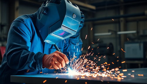
- When cutting metal with abrasive water jets, sparks are generally not generated, avoiding ignition accidents or explosions of harmful gases near the cutting area.
- During cutting, little or no heat is generated, and any heat generated can be quickly removed by the water jet, resulting in almost no heat-affected zones on the cutting surface.
- The cutting force on the cutting surface is small, so even when cutting thin sheets into molded parts, the cutting edge will not be damaged.
- The cutting is narrow, the material loss is small, the cutting surface is smooth and there are no burrs (a small amount of burrs may be produced if the cutting speed is too fast).
- There is almost no dust during cutting and no toxic gases are generated, making working conditions relatively clean.
- The cutting reaction force is small, so the nozzle can be easily moved by a mechanical arm.
- Full cutting is possible and cutting three-dimensional curved surfaces is easy, making it possible to cut parts of various shapes.
- Cutting conditions are easy to control, facilitating automatic adjustment and control via computers.
Disadvantages of abrasive waterjet machining include:
- The equipment requires high power.
- The nozzle wears out quickly.
- Not suitable for processing large parts or removing very large burrs.
- There is a lack of software designed specifically for waterjet machining.
Applications of abrasive waterjet technology include:
- Aerospace industry: Cutting special materials such as aluminum alloy, honeycomb structures, carbon fiber composites, layered metals or reinforced plastic glass, cutting aircraft blades with water jets without heat affected zones and work hardening , eliminating the need for further processing.
- Automotive manufacturing and repair industry: Cutting various non-metallic materials and composite components, such as dashboards, carpets, asbestos brake pads, door frames, automobile roof glass, interior decoration plates, rubber, gas tanks, plastic and other internal and external components.
- Arms industry: Cutting armor plates, rails, bulletproof glass, vehicle bodies, turrets, weapons and safe disassembly of various scrap projectiles.
- Forestry, agriculture and municipal engineering: Used for logging, bark removal, irrigation, feed processing, road maintenance, artisanal cutting and other tasks.
- Electronics and power industry: It can be used to shape and cut printed circuit boards and thin films, computer hard drives, floppy disks, electronic components, amorphous alloys, transformer cores and special cables that are difficult to cut by conventional methods.
- Machinery manufacturing industry: Using high-pressure water cutting instead of punching and shearing processes can not only save mold costs, but also reduce noise, vibration and improve material utilization. In addition, it can remove external alumina on workpieces, sand cores on castings, ceramic coatings, cutting burrs, gate risers and other parts, and can also cut gray cast iron parts that are difficult to cut by conventional methods .
- Other industries: Cutting marble, granite, tiles, ceramics, etc. in the building decoration industry, processing finished paper rolls, toilet paper, etc.
The development prospects of abrasive waterjet machining technology are:
Improve the reliability and service life of waterjet machining, especially the service life of important components such as high-pressure pumps, high-pressure hoses, gaskets and nozzles.
Optimization of process parameters to further improve efficiency, reduce abrasive consumption and reduce energy consumption, making costs more competitive.
Development of intelligent control to enable process parameters to be adaptively adjusted during processing, improving machining accuracy, and used to manufacture parts with certain precision requirements, achieving a technical and economic effect that can be comparable to machining plasma and laser.
Development trends of abrasive waterjet machining technology:
Continuously expanding the application scope of waterjet machining, from 2D cutting and deburring to hole machining and 3D surface processing.
Theoretical research on waterjet machining, especially the establishment of models for waterjet machining and the study of multiphase flow theory.
Research into machining miniature precision parts using abrasive waterjet technology, as well as the use of abrasive waterjet for turning and milling.