1. Flattening
The flattening (also known as hemming) method is illustrated in Figure 2-20. Initially, the edge of the sheet metal is bent into a 30° shape using a 30° bending die. Then the folded edge is flattened. Flattening can be carried out using a press, hydraulic machine or press brake.
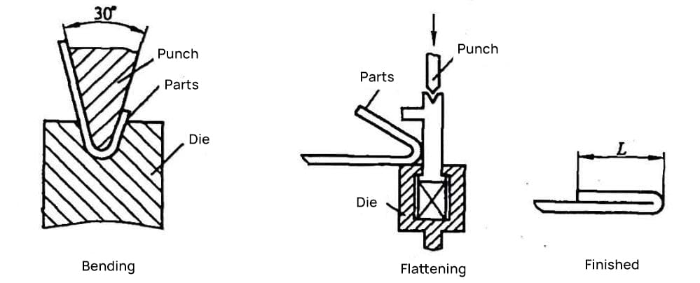
The minimum flattening width size L min for the press brake can be calculated using Equation (2-3) plus 0.5t (with t being material thickness), as shown in Equation (2-7):
I min = (B vmin – x) / 2 + f + 1.5t (2-7)
Common sheet materials suitable for straightening include stainless steel, galvanized sheet, and aluminum zinc sheet. Parts that require electroplating should not be used, as flat areas can cause acid entrapment, making treatment difficult.
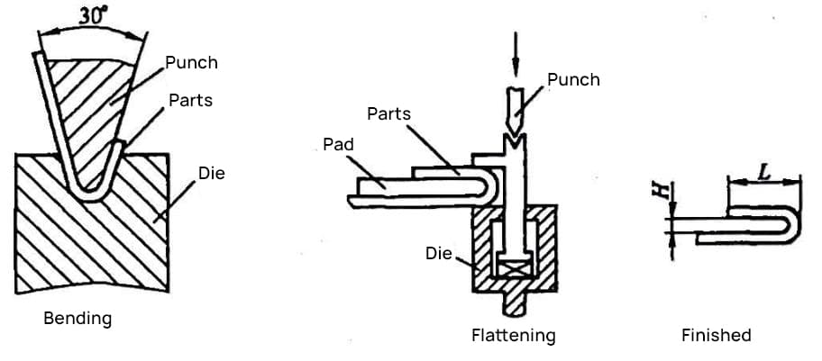
2. 180° U-shaped part bend
The process of bending a 180° U-shaped part is shown in Figure 2-21. Bend the sheet material at 30° first with a 30° bending tool, then flatten the folded edge and remove the spacer after flattening.
Spacer thickness H should be chosen from common sheet sizes (such as 0.5mm, 0.8mm, 1.0mm, 1.2mm, 1.5mm, 2.0mm), and it is not advisable choose a very large sheet thickness. When the opening of the 180° U part is large, a special mold must be used for bending.
The minimum fold edge size L min fold width can be calculated with Equation (2-3) plus H. The equation is as follows:
L min = (B vmin – x) / 2 + f + H (2-8)
3. Triple Fold Hem
The triple folding sheath is shown in Figure 2-22. Folding should be done first on the short side shown in the figure, then the U-shaped piece is formed using the previously mentioned 180° U-piece bending method, and finally the triple folding hem piece is formed using the flattening method.
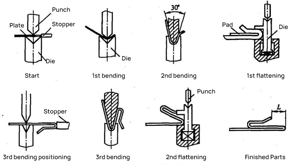
When designing and preparing processing technology for parts requiring a triple-fold dead edge, attention must be paid to the structural dimensions of all parts.
The structural dimensions must meet the minimum bending dimensions required by each stage and the minimum width dimension L min of the final flattened and compressed edge, avoiding unnecessary post-processing or manufacturing of special accessories.
The recommended value of the minimum width dimension L min of the flattened compressed edge is shown in Table 2-5.
Table 2-5 Minimum Final Flat Compressed Edge Width Dimension for Trifold Hemming (Unit: mm)
| Material thickness t | 0.5 | 0.6 | 0.8 | 1.0 | 1.2 | 1.5 | 2.0 | 2.5 |
| Minimum Compressed Edge Dimension L min | 4.0 | 4.0 | 4.0 | 4.0 | 4.5 | 4.5 | 5.0 | 5.0 |
Observation:
- The data in the table is experimental and for reference only.
- Even when the structure allows, it is not advisable to use the minimum size of the compressed edge.