Which process do you want to use to solve the problem of welding 270mm thick base metal, such as robot welding or narrow gap welding?
Next, we will examine how to produce a 4810mm x 4810mm x 270mm plate by butt welding 270mm Q235D steel plates.
1. Problems of welding large and thick sheets and measures to solve them
Requirements: Flatness requirements range from 8 to 10 mm to ensure the material properties of the steel plate after welding.
(1) Number and size of welded steel plates
It is constructed of three steel plates, with widths of 1,900 mm, 1,900 mm and 1,050 mm and lengths of 4,830 mm, which are joined together.
To account for welding shrinkage, a margin of 9 mm was reserved. However, after production was completed, it was found that the shrinkage was between 10 and 12 mm. Despite this, the machining tolerance of 25-30mm with a maximum error of 3mm does not affect its use in processing.
(2) Welding method and groove type
Common thick plate welding methods include electroslag welding, submerged arc welding, gas shielded welding, and stick arc welding.
Given the conditions of the project and the efficiency of the different welding methods, the welding method chosen was CO2 gas protected support welding with submerged arc welding and surface coating.
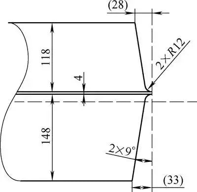
The groove shapes of thick plates are mainly Ⅰ-type, X-shape and U-shape, among others. After comprehensive comparison, the U-shaped groove was selected.
To facilitate the root cleaning process, an asymmetrical U-shaped groove was chosen. To ensure welding quality, the production of the channel must be completed by machining and must guarantee a size and surface roughness of 12.5μm.

(3) Pre-welding test
To guarantee the quality of the welding, a steel plate 1m long and 200mm thick was used for a welding test, which served not only to train the welders, but also to identify possible deficiencies in the operation process itself.
During the bottom welding test, it was observed that the opening at the unwelded end did not change significantly as the welded end was moved to the other end.
(4) Welding materials and parameters
An analysis of the main causes of cracks was carried out as follows:
① Hardening tendency
The material used is Q345D steel with an upper carbon content limit of 0.18%; wP, S ≤ 0.03%.
With a low tendency to harden and good weldability, this is not considered the main cause of cold cracks.
② Function of Hydrogen
The welding materials used were strictly dried and the workshop environment was kept dry.
Even though a small amount of hydrogen remains in the weld during welding, the content is low and is not considered the main cause of cold cracking.
③ Uneven temperature distribution in the thickness direction during welding can lead to large plastic deformation due to lateral compression;
Irregular contraction in the thickness direction during cooling after welding can easily cause angular deformation between the two connectors.
The selection principle for welding materials is that the alloy composition and strength performance of the weld metal must meet the lower limit specified by the base metal standard or reach the minimum performance index specified by the technical conditions of the product.
Therefore, it was decided to use THQ-50C welding wire with a diameter of 1.2mm, H10Mn2 submerged arc welding wire with a diameter of 4mm and SJ101 flux (preheated for more than 4 hours at 100°C before welding ). The welding parameters are as follows.
Welding parameters
| welding bead | arc voltage/V | welding current/A | degrees and diameter of welding wire/mm | welding speed | flow | grades |
| support welding | 26-32 | 140-180 | 1.2/THQ-50C | 300-400 | – | CO 2 arc welding with gas shielding |
| filler welding | 32-34 | 550 | 4/H10Mn2 | 200 | SJ101 | filler/AC welding |
| roof welding | 40-42 | 650 | 4/H10Mn2 | 334 | SJ101 | filler/AC welding |
Note: The temperature between layers in the welding area varies from 120 to 180°C.
Lastly, reverse deformation is employed to control the deformation that occurs during the welding process.
In the welding construction process, due to the reverse deformation caused by welding, it is necessary to promptly rotate the part and weld the other side, allowing cyclic operation to control the deformation.
(5) Heat Treatment
Preheating the part is mandatory before welding and is crucial to ensure uniform heating of the part.
After several attempts, it was decided to drill several evenly spaced holes in one side of a 4.8 m long pipe.
The tube was then sealed with a gas cutting nozzle which was welded to the tube and heated using gas ignition.
Two pieces were made so that both sides of the weld could be heated simultaneously.
At the end of the welding process, a large amount of welding residual stresses are generated within the part.
To avoid delayed cracking and deformation during processing, anti-stress annealing in the furnace must be carried out after welding.
2. Implementation
Place the sheet material 1 to 1.2 meters above the ground, with an anti-warping angle of 1 to 1.5 degrees and a top gap of approximately 2mm.
Before welding, the 200mm area on each side of the back of the weld will be heated simultaneously at several points to ensure a uniform preheating temperature. The front side preheating temperature must be between 90 and 120°C.
The side with the large groove will be welded first, using arc welding with CO2 gas shielding for the base.
At this point, the deformation of the part furthest from the control board must be measured (with a minimum of 4 measuring points).
When the deformation of the part is between 1 and 1.2 degrees (calculated as A), that is, the measuring point is above the plane value ≤ A, the part must be turned over.
It is important to note that when welding on a large, thick plate, the workpiece must be turned over and welded on both sides of the plate with concave welding ribs to prevent lifting when cracks occur.
The control submerged arc fill weld width should be less than 18 mm to reduce defects. The width of the weld must be the same.
After turning the workpiece, carbon arc gouging is required to remove the bottom weld, reveal the weld metal, and smooth the surface. Then, submerged arc welding can begin.
During the welding process, the deformation of the far side plate will be measured continuously.
When the reverse deformation reaches 0 degrees, the concave weld ribs will be removed, leaving only three evenly distributed weld ribs. When the reverse deformation reaches (A-5) mm, the part will be reversed again.
After turning and fixing the part, the welding ribs will be removed and the deformation of the plate will be observed (the observation values are small, about 2 mm).
Submerged arc welding will then begin and when the reverse deformation is less than or equal to 10 mm (measured as described above), the part will be rotated again.
This process should be accompanied by high-temperature ultrasonic flaw detection, if available, to reduce the amount of rework required for final defects.
After the part is rotated, submerged arc welding will be carried out while the reverse deformation is controlled within 5mm.
The part will be turned over and welded on the other side until the entire welding process is completed.
After welding, the part will be kept warm for 6 hours.
After natural cooling, the weld surface will be smoothed, ultrasonic tests will be carried out, and the entire part will undergo stress relief annealing in the oven at 620℃ for 10 hours.
During annealing, the deformation of the large plate due to its own weight must be taken into account, and methods such as self-weight and external gravity can be used to flatten the plate.
After the welded parts undergo stress relief annealing and cool to room temperature, welding and flatness defects will be tested and the next steps will be taken if the requirements are met.
The other steel plate will be welded to the welded steel plate using the same welding method and steps described above.
After the general welding is completed, the weld will be kept hot for 6 hours, cooled naturally and subjected to ultrasonic testing. Then, the entire part will undergo stress relief and annealing again.