The overlay welding process has high efficiency and low equipment cost, and is widely used in the manufacture and repair of parts, the modification of material surfaces, and the flexible production of small and medium batches of metal components.
In the actual use of underground engineering equipment, the equipment is subjected to complex forces and adverse working conditions.

For example, the tunnel boring machine is a tunnel boring machine that uses the shielding method. During the use of the underground tunnel boring machine, the cutting head and related components such as cutting head protection blocks, cutting seat and edge scraper seat inevitably suffer wear.
The overlay welding process is not only applied to the remanufacturing and repair of worn cutting head components, but also to the additive preparation of wear-resistant layers and networks of wear-resistant parts in order to increase the wear resistance of parts . In actual production, to improve production efficiency, a higher welding current is often used.
However, due to the limitations of overlay welding quality, when the current is too large, the dilution rate will increase, which may cause defects such as alloy composition segregation and loss of liquid metal during the overlay welding process.
On the contrary, when the welding current in overlap welding application is relatively small, it will lead to lower production efficiency.
Double wire welding, as an efficient welding method, has been increasingly concerned by people. Double wire welding can achieve high weld deposition rate and also improve the composition and crystallization of the weld seam by using the temperature field and thermal cycle of double wire welding, thereby improving the microstructure and performance of the welding layer overlay.
Therefore, exploring the application of double wire welding in overlap welding, balancing the formation and quality of overlap welding, and improving the actual production efficiency are of great significance to the practical technical application of overlap welding.
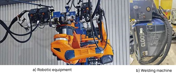
Overlay Welding Additive Manufacturing System
The welding power source used in the experiment is the QINEO PULSE 600 from CLOOS. When using the QINEO welding machine to perform small current pulse welding, the spatter is small and the formation is beautiful.
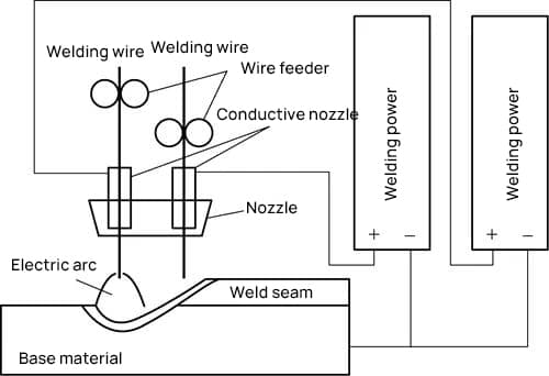
Based on this, a double-wire welding process is developed that not only considers the quality of the weld seam, but also greatly improves the welding deposition efficiency. The double wire welding equipment adopts a double wire gun structure, in which the two wires are constantly melted in the same pool.
The front wire provides preheating for the rear wire, and the rear wire reheats the front wire, which improves the microstructure and performance of the overlay welding layer.
Because the two wires are isolated from each other, a variety of flexible and diverse combinations can be used.
This not only allows independent adjustment of the parameters of the two wires, but also allows the selection of two different diameters and different wire materials according to specific application requirements, thus covering a wide range of applications.
The working principle of double wire welding in a shared melting pool is shown in Figure 1.
Compared with single-wire welding in the experiment, single and double wires are freely exchanged through the double-wire welding system, while other welding methods and shielding gas conditions remain unchanged.
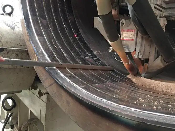
In the experiment, the CLOOS QINEO PULSE 600 welding machine is used as the welding power source to melt the overlap welding wire, and the CLOOS robot is equipped with a double-wire welding gun to ensure the accuracy of the overlapping welding welding gun during welding and to control the welding speed. Some parts of the hardware and overlay welding system are shown in Figure 2.
Experimental methods and processes
The base material used in the experiment is Q235 steel, with a thickness of 12mm, and its main chemical composition is shown in Table 1. The experiment uses wear-resistant welding wire UTP AF ROBOTIC 600, with model DIN 8555: MSG 6 -GF-60-GP, and its main chemical composition is shown in Table 2. The diameter of the welding wire is 1.2 mm. The shielding gas used is 80% Ar + 20% CO 2 .
Table 1: Chemical composition of the base material (mass fraction) (%)
| W | Yes | Mn | s | P |
| 0.22 | 0.35 | 0.14 | 0.045 | 0.045 |
Table 2: Chemical composition of the welding wire (mass fraction) (%)
| W | Yes | Mn | Cr | Mo |
| 0.57 | 2.56 | 0.54 | 8.96 | 0.01 |
Traditional welding parameters for single-wire welding are shown in Table 3.
Table 3: Welding Parameters for Overlap Welding
| IA welding current | IV arc voltage | Welding speed /(cm/min) |
Dry stretching /mm |
gas flow rate (L/min) |
Pendulum welding parameters |
| 164 | 19.8 | 18 | 15 | 18 | / |
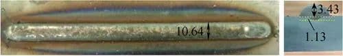
The welding effect is shown in Figure 3, with a weld width of 10.64 mm, a weld height of 3.43 mm, and a fusion depth of 1.13 mm.
For the double-wire jacket welding test, the welding method and shielding gas conditions were consistent with those for single-wire jacket welding. The dry elongation in the experiment was 20mm. Using the orthogonal experimental method, the front wire current, rear wire current and welding speed were adjusted to conduct a three-factor, four-level orthogonal experiment. Weld width and height data were obtained by observing and measuring weld formation. Some welding parameters and weld size are shown in Table 4.
Table 4: Welding parameters for double wire welding
| Front wire welding current A |
Front wire arc tension V |
Back wire welding current /A |
Back wire arc tension V |
Welding speed /(cm/min) |
Weld bead width /mm |
Weld bead height /mm |
| 120 | 20.4 | 100 | 20.9 | 30 | 8.92 | 2.75 |
| 140 | 21.3 | 100 | 20.9 | 35 | 8.93 | 2.83 |
| 160 | 22.2 | 100 | 20.9 | 40 | 9.01 | 3.02 |
| 180 | 23.0 | 100 | 20.9 | 45 | 9.02 | 3.45 |
| 120 | 20.4 | 120 | 21.2 | 30 | 12.03 | 3.05 |
| 140 | 21.3 | 120 | 21.2 | 35 | 11.12 | 3.25 |
| 160 | 22.2 | 120 | 21.2 | 40 | 11.23 | 3.08 |
| 180 | 23.0 | 120 | 21.2 | 45 | 12.24 | 3.52 |
| 120 | 20.4 | 140 | 22.4 | 30 | 11.84 | 3.06 |
| 140 | 21.3 | 140 | 22.4 | 35 | 12.26 | 3.07 |
| 160 | 22.2 | 140 | 22.4 | 40 | 12.88 | 3.13 |
| 180 | 23.0 | 140 | 22.4 | 45 | 13.02 | 3.21 |
| 120 | 20.4 | 160 | 23.3 | 35 | 12.72 | 2.86 |
| 140 | 21.3 | 160 | 23.3 | 40 | 13.23 | 2.88 |
| 160 | 22.2 | 160 | 23.3 | 45 | 1:90 p.m. | 3.02 |
| 180 | 23.0 | 160 | 23.3 | 50 | 13.92 | 3.01 |
When analyzing the data of welding current, weld width and weld height of double wire welding, it can be seen that when the welding current and welding speed change, considering the fluctuation of weld width and height caused by variations in weld formation and measurement errors, the change in weld height is not significant, while the change in weld width is more prominent.
When the welding speed is kept constant at 35 cm/min, 40 cm/min and 45 cm/min respectively, the relationship between the weld width and the front/back wire current is adjusted with a surface equation.
The function of the established surface equation model is:
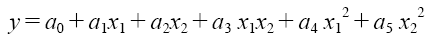
In the formula:
y – weld width (mm);
x1 – front wire current (A);
x2 – rear wire current (A);
a0, a1, a2, a3, a4 and a5 – coefficients.
When the welding speeds are 35 cm/min, 40 cm/min and 45 cm/min, the coefficients a3, a4 and a5 in the equation are approximately 0. When the speed is 35 cm/min, the surface fit equation is :
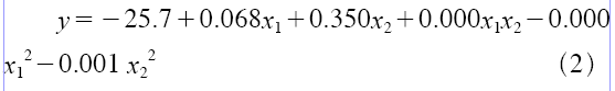
Thus, it can be inferred that the terms x1x2, x12 and x22 in the fitting equation have a relatively small impact on the value of y.
Using the fitting formula to test the experimental data at the speeds of 40cm/min and 45cm/min, and inputting the current values of the front and rear wires to obtain the value of y, the calculated values of y and the actual weld width have an error quite uniform.
The relationship between the weld width and the double wire welding current can be obtained from formula (2), as shown in figure 4.
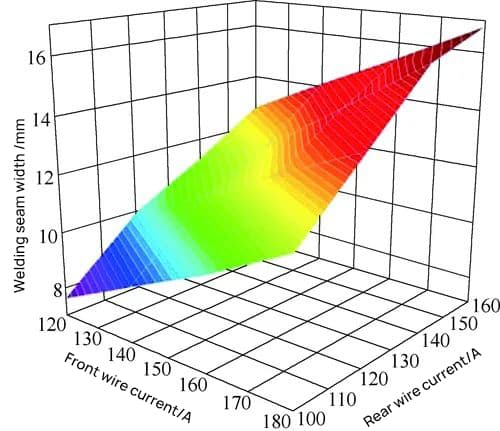
According to formula (2), the weld width is positively correlated with the front and rear wire current, and approaches a linear relationship, with the effect of the rear wire current being greater. In the actual welding process, the front wire has a preheating effect on the rear wire, while the rear wire has a significant effect on the weld pool.
The molten pool is influenced by the back wire arc force and continuous heat, which increases the flow tendency of the metallic liquid in the molten pool and ultimately leads to an increase in the weld width.
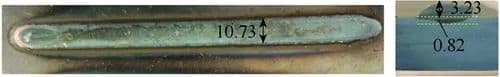
When the welding currents of the double wire surface are 140A and 120A, and the welding speed is 30cm/min, the weld width is 10.73mm, the height is 3.23mm, and the penetration depth is 0.82mm. The surface effect is good, as shown in figure 5.
At this time, the size of the double-wire surface is similar to that of the single-wire surface, and the penetration depth of the double-wire surface is smaller. The heat-affected zone is reduced, the degree of reaction with the base metal is reduced, and the dilution rate decreases, which is beneficial to improving the coating quality.
The welding speed is increased by more than 50% compared with traditional single-wire surface, significantly improving production efficiency.
Microstructure Testing and Analysis:
For the double-wire and single-wire coating samples, a coating sample of 20 mm × 10 mm × 10 mm was obtained by cutting and its performance was tested and analyzed. Welding parameters are shown in Table 5.
Table 5 Main welding parameters of test specimens
| Project | Welding current AI |
Arc voltage 4 |
Welding speed (cm/min) |
| Double Wire Welding Test 1 | 120 (front) 100 (rear) |
20.4 (front) 20.9 (rear) |
30 |
| Double Wire Welding Test 2 | 120 (front) 120 (rear) |
20.4 (front) 21.2 (rear) |
30 |
| Double Wire Welding Test 3 | 140 (front) 120 (rear) |
21.3 (front) 21.2 (rear) |
30 |
| Single Wire Welding Sample | 164 | 19.8 | 18 |
Microhardness Test
A 600HVS-1000AVT type image microhardness tester from China was used to perform microhardness testing on the samples. The Vickers penetrator was shaped like a four-sided pyramid. The load was 300g (2.94N) and 100g (98N), and the waiting time was 15s.
The double-wire and single-wire welding samples were measured along the fusion line, starting from the weld surface as the starting point of measurement, with an interval of 1 mm for point measurement.
Multiple measurements were made at each measuring point and the average value was obtained, resulting in a transverse mean microhardness distribution curve (see Figure 6).
From Figure 6, it can be seen that in the position of the weld surface, the hardness values of the double-wire and single-wire welding samples are similar.
From the surface of the weld bead to a distance of 3 mm from the surface of the weld bead, the hardness value of the double wire welding sample remains basically unchanged, with the hardness value of the double wire welding sample 2 increasing slightly, while the hardness value of the single wire welding sample gradually drops.
At a distance of 3-5 mm from the surface of the weld bead, the hardness values of the double-wire and single-wire welding samples decrease rapidly until they approach the hardness of the matrix (140HV0.2).
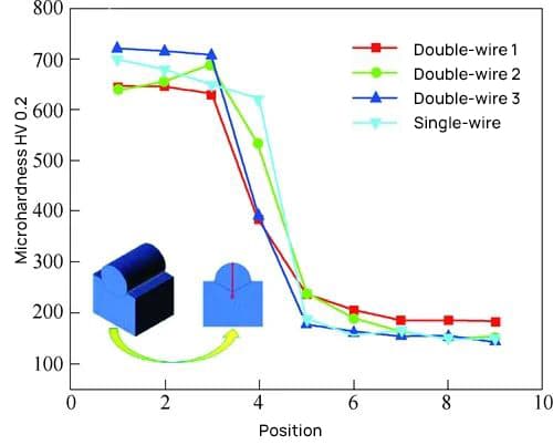
From the microhardness tests, it can be seen that the surface hardness of the coating layer of the double wire welding sample is above 700HV0.2, meeting the hardness requirements of actual coating applications.
During single-wire surface and double-wire surface, the alloying elements of the surface layer diffuse towards the base metal, and the closer the surface layer is to the base metal, the more obvious the decrease in hardness will be.
From the hardness distribution curve, it can be inferred that during single-wire coating, the diffusion process is relatively stable and the hardness value is significantly affected by distance.
As the coating layer approaches the base metal, the hardness value gradually decreases.
In double wire cladding, the use of temperature fields and thermal cycles in double wire welding improves the element diffusion process, optimizes the structure and properties of the coating layer, and within a certain range of distance from the layer surface coating, the hardness value remains basically unchanged.
Friction and wear performance tests
The double wire coating sample and the single wire coating sample were subjected to dry sliding wear tests under the same environmental conditions (temperature: 28-30°C, humidity: 60%) on the ball-on-disc machine HT1000.
A Si3N4 sphere with a diameter of 4mm was selected for the test, and the load was set at 10N, the sliding speed was set at 59mm/s, and the wear time was 30 minutes. The amount of wear was measured using an FA2104 precision scale.
Observing the testing process, it was found that under lower loads and lower speeds, double wire welding sample 2 suffered a short period of light wear combining abrasive wear and plastic deformation, but stabilized after about 1 minute.
The trend of the friction coefficient curve changed similarly to the single-wire welding sample. The friction coefficient of double wire welding sample 1 fluctuated greatly, and double wire welding sample 3 entered the friction steady state stage after a long period of time.
The friction coefficient of the single-wire welding sample was the smallest, fluctuating around 0.4, and the friction coefficient of double-wire welding was 0.6-0.8.
Due to the low temperature of the sample, no melt wear was observed on any of the samples. The friction and wear performance test results are shown in Figure 7.
From Figure 7b, it can be seen that the double wire welding sample has extremely small friction loss, while the friction loss of the single wire welding sample is approximately 1.5g.
The results of friction and wear performance tests indicate that, compared with the single-wire surface, the double-wire surface results in an increase in the coefficient of friction and a decrease in the amount of wear.
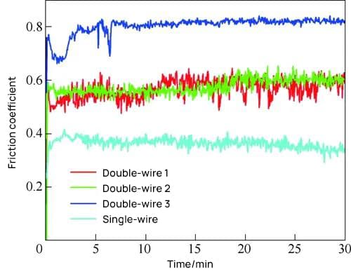
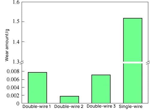
Figure 7: Results of friction and wear performance tests of the samples.
Wear Surface Structural Performance Test
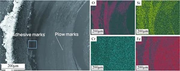
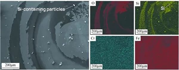
Material wear is a complex process. To confirm the reason for the loss of wear amount, the morphology and component analysis of the worn surface of the double-wire deposited welding sample and the single-wire deposited welding sample after friction test were carried out using scanning electron microscope ZeissSigma (SEM) and Smartedx Energy Dispersive Spectroscopy (EDS).
The SEM and EDS images of the worn surface of the double-wire deposited welding sample and the single-wire deposited welding sample after friction test are shown in Figure 8.
It can be seen from Figure 8 that the surface of double wire welding sample 1 is mainly composed of shallow and fine plow marks with a small amount of adhesion marks.
At this time, the wear is mainly abrasive. The surface adhesive area of the single wire welding sample increases and there are many white particles.
Through EDS comparison and analysis, it is determined that the white particles are mainly compounds containing Si elements. The silicon compound is mainly due to the high hardness of the counter-friction pair in the dry friction wear process.
The wear particles attached to the surface of the sample, at this time, the wear is mainly abrasive wear and adhesive wear.
It is inferred that the metal crystals that form silicon compounds during single-wire deposition have poor anti-adhesive properties, which increases adhesive wear during friction and increases wear.
During double wire deposition, the composition and crystallization of silicon compounds are improved, which reduces wear.
Conclusion
In the welding operation, the double wire deposit welding method is adopted. By adjusting the welding parameters and controlling the formation size of the deposit layer, and utilizing the temperature field and thermal cycle characteristics of double wire welding, the composition and crystallization of the weld are improved and the dilution rate is improved. reduced.
This improves the organizational performance and wear resistance of the deposit layer to a certain extent, and the efficiency of deposit welding is greatly improved.
The results of this study have reference value for the application of deposit welding in underground engineering equipment, as well as the application of double wire welding in the field of deposit welding and arc additive manufacturing.