Springs are widely used in the mechanical and electronic industries due to their elastic properties.
When a spring is subjected to a load, it undergoes significant elastic deformation, transforming mechanical work or kinetic energy into stored strain energy.
After discharge, the spring returns to its original state, with the stored strain energy being converted back into mechanical work or kinetic energy.
The relationship between the spring load and its deformation is called spring stiffness. The greater the stiffness, the stiffer the spring becomes.
1. Spring function
Spring functions include:
- Cushioning and damping, such as the damping springs used in car and train suspensions and various damping systems.
- Control the movement of mechanisms, such as valve springs in internal combustion engines and control springs in clutches.
- Store and release energy, like clock springs and gun lock springs.
- Measurement of force, such as springs in spring balances and dynamometers.
2. Classification of springs
Springs can be categorized based on their tension nature into four types: tension springs, compression springs, torsion springs and bending springs.
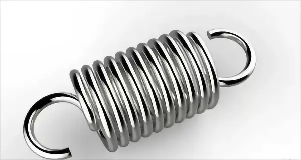
A tension spring is a type of helical spring that undergoes axial tension.
These springs are typically made from circular cross-section materials.
When not subject to a load, the coils of a tension spring are generally tightly wound with no gaps between them.
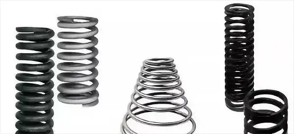
A compression spring is a type of coil spring designed to withstand compressive forces.
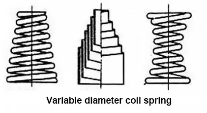
The cross-section of compression springs is typically circular, but they can also be made of rectangular or multifilament steel.
These springs are usually equal pitch and there is a small space between the coils.
When subjected to an external load, the compression spring compresses, deforms and stores energy in its deformation.
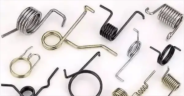
Torsion springs are a type of coil spring.
They are capable of storing and releasing angular energy or of holding a device in a static position by rotating the force arm around the central axis of the spring body.
The ends of a torsion spring are attached to other components, and when these components rotate around the center of the spring, the spring pulls them back to their original position, generating torque or rotational force.
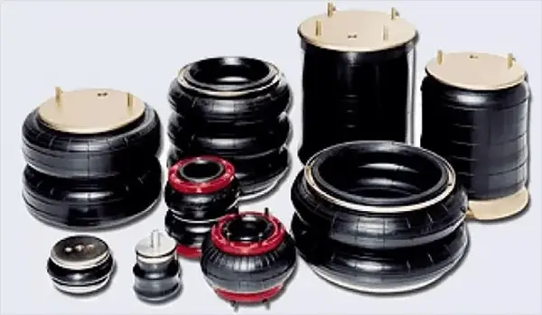
In addition to the common types of springs, there are also two unconventional types: pneumatic springs and carbon nanotube springs.
A pneumatic spring is a non-metallic spring that uses the compressibility of air to create an elastic effect by adding pressurized air into a flexible closed container.
When used in high-end vehicle suspension systems, air springs greatly improve ride comfort, making them widely used in automobiles and railway locomotives.
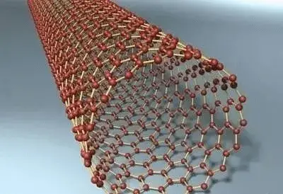
A carbon nanotube spring is created by spinning technology, starting with the preparation of a carbon nanotube film.
With a diameter of hundreds of microns and a length of a few centimeters, carbon nanotube springs have numerous potential applications, including retractable conductors, flexible electrodes, micro strain sensors, supercapacitors, integrated circuits, solar cells, field emission sources, energy dissipation fibers and more. They are also expected to be used in medical devices such as tension-sensing bandages.
3. Spring material and allowable tension
During operation, springs are often subjected to alternating and impact loads and are forced to undergo significant deformation. As a result, the material used to make springs must have high tensile strength, elastic limit, and fatigue resistance.
Furthermore, the manufacturing process must result in sufficient hardenability, resistance to decarburization and good surface quality.
Common spring materials and allowable shear stress
| Materials science | See shear stress (τ)/MP for details | Shear modulus of elasticity G/MPa | Recommended Operating Temperature/℃ | |||
|---|---|---|---|---|---|---|
| category | Code | Type I spring | Type II spring | Type III spring | ||
| Carbon Spring Steel Wire | Group I II, II and III | 0.3s | 0.45 | 0.5 | 80,000 | -40~120 |
| 65 minutes | 420 | 560 | 700 | 80,000 | -40~120 | |
| Alloy Spring Steel Wire | 60Si2Mn | 480 | 640 | 800 | 80,000 | -40~200 |
| 65SiMnWA | 570 | 760 | 950 | 80,000 | -40~250 | |
| 50CrVA | 450 | 600 | 750 | 80,000 | -40~210 | |
| stainless steel wire | 1Cr18Ni9 | 330 | 440 | 550 | 73,000 | -250~300 |
| 4Ch13 | 450 | 600 | 750 | 77,000 | -40~300 | |
Observation:
- Springs can be classified into three categories based on the number of cycles they undergo under load: Type I, with n > 10 6 ; Type II, with n = 10 3 ~ 10 5 and under impact load; and Type III, with n < 10 3 .
- The allowable tension for the shackle tension springs is 80% of the value listed in the table. If the spring is subjected to strong pressure treatment, its allowable tension can be increased by 20%.
- Carbon cable spring steel is divided into four groups based on their mechanical properties, with Group 1 having the highest tensile strength, Group II second, Group III having the lowest, and Group IV having the same tensile strength as Group II, but better plasticity.
The Sb of carbon cable spring steel wire can be found in the table.
Strength of carbon spring steel wire
| Code | Congressperson | |||
|---|---|---|---|---|
| Group I | Group II | Group III | ||
| Wire diameter d/Mn | 0.2 | 2700 | 2250 | 1750 |
| 0.3 | 2700 | 2250 | 1750 | |
| 0.5 | 2650 | 2200 | 1700 | |
| 0.8 | 2600 | 2150 | 1700 | |
| 1 | 2500 | 2050 | 1650 | |
| 1.5 | 2200 | 1850 | 1450 | |
| two | 2000 | 1800 | 1400 | |
| 2.5 | 1800 | 1650 | 1300 | |
| 3 | 1700 | 1650 | 1300 | |
| 3.6 | 1650 | 1550 | 1200 | |
| 4 | 1600 | 1500 | 1150 | |
| 4.5 | 1500 | 1400 | 1150 | |
| 5 | 1500 | 1400 | 1100 | |
| 5.6 | 1450 | 1350 | ||
| 6 | 1450 | 1350 | 1050 | |
| 7 | 1250 | 1000 | ||
| 8 | 1250 | 1000 | ||
4. Spring manufacturing
The process of producing a coil spring involves rolling, creating hooks or completing end-face rings, heat treating, and performance testing.
In large-scale production, springs are wound using a universal automatic winding machine. For individual pieces or small batch production, they are made on a traditional lathe or manually. When the diameter of the spring wire is 8 mm or less, a cold winding method is usually used.
Heat treatment is required before winding, and low temperature tempering is required after winding. When the diameter is greater than 8 mm, a hot winding method must be employed (with temperatures ranging from 800°C to 1000°C). After hot winding, the spring must be quenched and tempered at medium temperatures.
After the spring is formed, a quality inspection of the surface must be carried out to ensure that it is smooth and free from defects such as scars, decarburization and other imperfections. Springs that will be subjected to variable loads must also undergo surface treatment, such as shot peening, to improve their fatigue life.
5. Final spring structure
The effective number of turns N that participate in the deformation of the compression spring is crucial to ensure that the spring functions uniformly and that its center line is perpendicular to the end face.
To achieve this, there are 3/4 to 7/4 turns on both ends of the spring that play a rigid support role, known as dead circles or support rings. These turns do not participate in deformation during work.
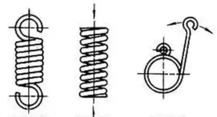
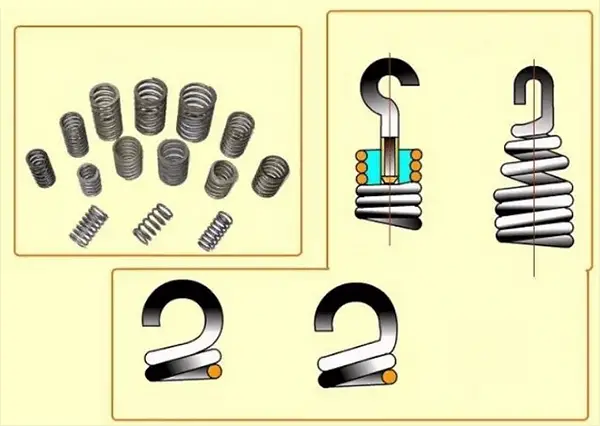
The tension spring is equipped with a hook at its end for installation and loading, and there are four common types of end structures: semicircular shackle, circular shackle, adjustable hook and swivel hook.
Semicircular and circular shackles are easy to manufacture and widely used, but due to the high bending stress at the hook transition, they are only suitable for springs with spring wire diameter d ≤ 10mm. On the other hand, adjustable and swivel hooks are under good tension condition and can be rotated to any position for easy installation.
6. Calculation of spring tension
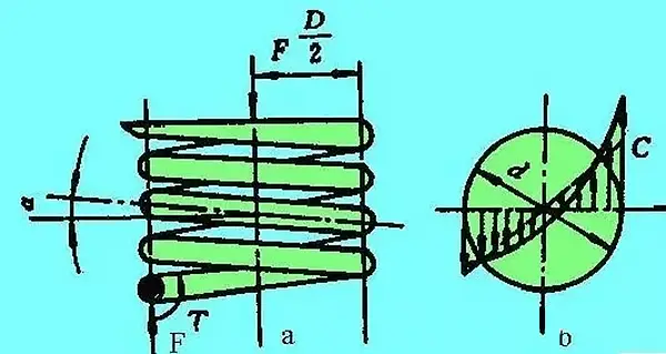
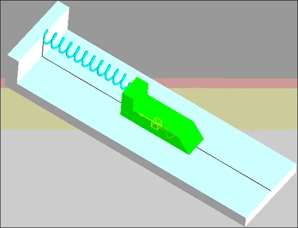
Compression Spring Stress Analysis
Figure (a) shows the cylindrical helical compression spring, which supports the axial working load F.
Analysis of the section method reveals that the section of the spring wire is subjected to a shear force F and a torque T, which is equal to F times D divided by 2. The torque results in a shear stress, which can be calculated as follows:
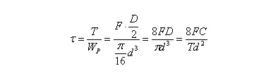
If we take into account the impact of the shear stress generated by the shear force F and the spiral curvature of the spring wire, the maximum shear stress t can be found on the inner side of the spring, as depicted in figure (b). Its value and resistance conditions are as follows:

Where,
C – winding ratio,
C = D / D, which can be selected according to table 1
K — spring curvature coefficient,
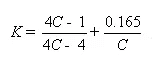
K can also be found directly in table 2.
It is known from the table that the higher C, the smaller the influence of K on T;
F — spring working load, N;
D — spring diameter, mm;
D – material diameter mm.
Table 1 recommended winding ratio values
| Steel wire diameter. D | 0.2~0.6 | 0.5~1 | 1.1 ~ 2.2 | 2.5~6 | 7~16 | 18~50 |
| C=D/d | 7~14 | 5~12 | 5~10 | 4~9 | 4~8 | 4~6 |
Table 2 Curvature coefficient K
| C winding ratio | 4 | 5 | 6 | 7 | 8 | 9 | 10 | 12 | 14 |
| K | 1.4 | 1.31 | 1.25 | 1.21 | 1.18 | 1.16 | 1.14 | 1.2 | 1.1 |
In equation 1, the formula for calculating the diameter of the spring steel wire according to the resistance condition can be obtained by replacing f with the maximum working load F2 of the spring:
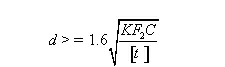
The method for calculating the resistance of a tension spring is identical to that of a compression spring.
7. The spring is not in place and the reason for the failure
In practical work, it is common to encounter situations where the spring cannot push the moving object to the designated position, causing the calculated free length of the spring to become shorter.
The cause of this problem is a lack of initial compression treatment, which involves compressing the spring to its compression height or pinch height using a significant amount of force (if necessary) and then releasing it so that it returns to its free length original.
The amount by which the spring has been shortened is called the “initial compression contraction.”
Typically, after being subjected to compression 3 to 6 times, the length of the spring will no longer decrease and it will have “settled in position”.
It is important to note that after undergoing initial compression, the spring is permanently deformed.
8. Spring Precautions
In practical applications, a compression spring must be able to maintain its working length even if it is subjected to forces that exceed the elastic limit of its material.
As a result, the length of the finished spring should equal the calculated length of the spring plus the initial compression contraction. This will prevent the spring from staying in place and reduce the risk of dangerous tension when the spring coils are squeezed together, leading to abnormal spring deflection.
During the heat treatment of the finished spring, especially in the quenching and tempering process, it is essential to place the part horizontally (lying down) in the oven to prevent the spring from becoming shorter due to its own weight, which could result in improper operation.