1. Overview
WC67Y-250/4000 hydraulic press brake is designed to bend metal sheets with high labor productivity and bending accuracy. It offers stability, reliability and ease of operation, with gradual or continuous displacement options.
This hydraulic press brake maintains consistent pressure throughout the work stroke, ensuring even distribution of force. Users can easily equip it with different molds to obtain the required sheet metal bending shape.
However, it is important to note that the return motion speed of this press brake is several times faster than the bending process, allowing for greater production efficiency. However, it is crucial to ensure that the press brake cylinder does not fall too quickly, causing it to become out of sync and potentially affecting the quality of the final product.
2. Dyssynchrony cause analysis
1) Piston cylinder analysis:
The main reason for the problem is internal leakage in the piston cylinder. The gap between the piston and the oil cylinder is too large, causing leakage. However, the leakage in the left and right cylinders is not uniform, resulting in different movement speeds of the two cylinders.
2) Oil inlet pipeline analysis:
Figure 1 illustrates the press brake process descending rapidly. The oil pump supplies oil to the oil cylinder through the synchronous valve, while the upper oil tank 1 supplies oil to the oil cylinder through the one-way valve 2 through the natural height difference. These two types of oil supply oil to the upper chamber of the oil cylinder, which makes the oil cylinder descend quickly.
Due to the approximate flow in the valve circuit after the timing valve, only the flow from the tank through check valve 2 to oil cylinder 3 is taken into account.
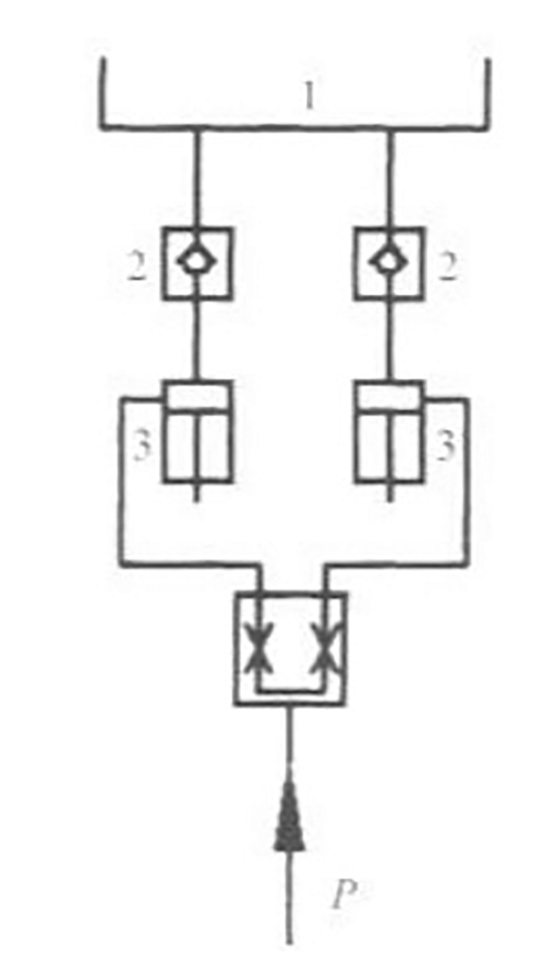
1- Oil tank; 2 – Check valve; 3 – Oil cylinder.
Fig. 1 Oil cylinder oil supply analysis
Figure 2 shows the structure of check valve 2.
P 1 denotes the inlet pressure while P 2 represents the outlet pressure.
Considering the inlet pressure to both check valves, P 1 can be considered as atmospheric pressure, making them equal.
Since P 1 is constant, the flow rate Q through the check valve increases with an increase in the pressure difference (PP 2 ).
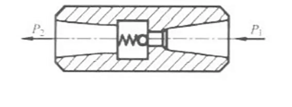
Fig. 2 Check valve structure
It is evident from the above that the two hydraulic cylinders will not be completely synchronized when started. As a result, the pressure in the upper chamber of the two cylinders, indicated as P, will not be the same. This pressure difference between the front and back of the two check valves will also not be the same.
Consequently, the flow from the oil cylinder through the one-way valve to the two cylinders will not be equal. This imbalance in flow will result in desynchronization of the movement of the two cylinders.
3) Oil return pipeline analysis:
When the press brake descends rapidly, the movement damping in the oil return circuit may not be equal, causing a difference in back pressure in the lower piston chamber. Consequently, the return flow rate of the two cylinders may not be the same, resulting in the rapid descent speed of the two cylinders being unequal and therefore out of synchronization.
3. Solution
(1) To ensure equal leakage in both hydraulic cylinders, it is important to maintain consistency in the selection accuracy of left and right pistons, cylinders and other parts (including dimensional accuracy and position accuracy such as coaxiality, roundness, etc.). Furthermore, the hydraulic circuits of the two hydraulic cylinders must be designed as similar as possible.
(2) To ensure equal flow through the two check valves in the oil inlet pipe, it is necessary to strive so that the center of gravity of the movable structure is located at the geometric center of the two cylinders. In addition, the mechanical damping between the piston and the piston rod and between the piston rod and the end cap should be as close as possible to ensure similar mechanical damping of the two piston cylinders when they fall quickly.
(3) For the oil return pipeline, it is necessary to ensure that the return flow of the two cylinders is equal, making the return oil resistance of the oil return pipeline similar. This involves ensuring that the pipe diameter, pipe length, pipe bend number and pipe bend angle are basically the same.
(4) The press brake uses a mechanical rack and pinion drive for force synchronization. The device is shown in Figure 3, with the rack installed on both sides of the connecting frame and engaged with the rack gear. The rack serves as an orientation device and error correction is done through gear engagement. As long as the manufacturing accuracy of the rack and gear is guaranteed, the two working cylinders of the press brake can achieve a very high level of synchronous accuracy.
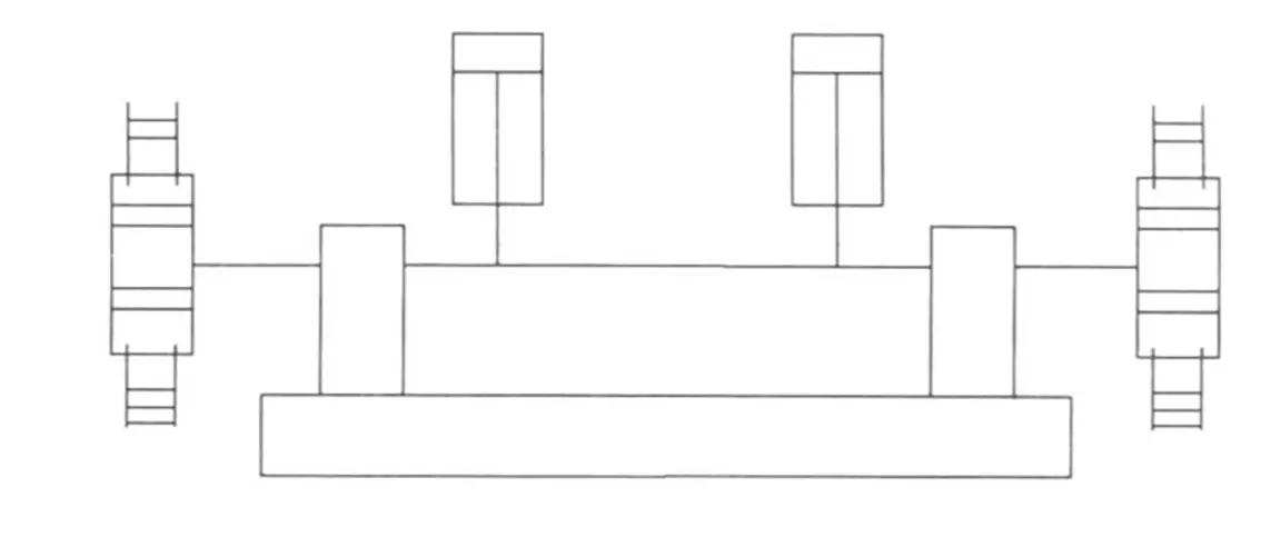
Fig.3 Schematic diagram of rack drive with forced synchronization
4. Effect
Through the collaboration of users, designers and manufacturers, the entire manufacturing, assembly and commissioning process has been significantly improved. As observed in actual usage, the structure is simple and compact, and the operation is stable with minimal noise. As a result, the quality of bent steel sheets is guaranteed and the bending efficiency meets the required standards.