1. Characteristics of the manual tungsten inert gas (TIG) welding process
(1) Working principle
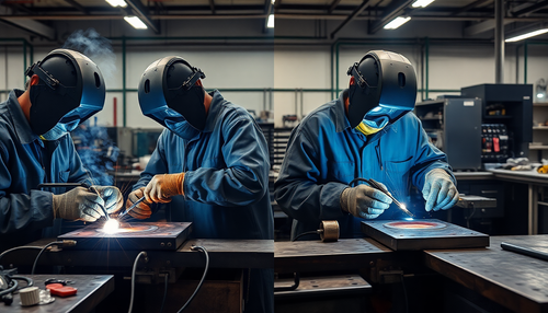
Tungsten inert gas (TIG) welding is a gas shielded welding method that uses a tungsten rod as the electrode and argon as the shielding gas.
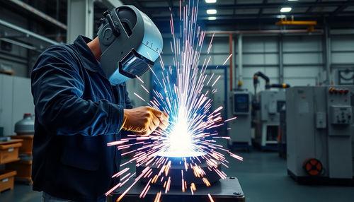
An electric arc is generated between the tungsten electrode and the workpiece, and the argon gas flow from the welding torch forms a hermetically sealed layer in the arc area.
This isolates the electrode and the pool of molten metal from the air, preventing intrusion. Heat from the arc is used to melt the base metal and filler wire to form a molten pool, which solidifies into a weld seam upon cooling.

Argon, being an inert gas, does not react chemically with the metal, therefore it adequately protects the molten metal pool from oxidation.
Argon also does not dissolve in molten metal at high temperatures, which prevents the formation of gas holes in the weld seam. Thus, the protective effect of argon is effective and reliable, producing high quality weld beads.
During welding, the tungsten electrode does not melt, therefore TIG welding is also called non-consumable electrode arc welding. Based on the energy source used, TIG welding is divided into direct current (DC), alternating current (AC) and pulsed types.
(2) Process Characteristics
1) Advantages of TIG welding compared to other arc welding methods
The. Superior Protection
The high-quality weld seam is due to the non-reactivity of argon with metals and its insolubility in them. The welding process is essentially a simple process of melting and crystallizing metal, resulting in a purer, higher quality weld seam.
B. Minimum deformation and stress
The argon gas stream compresses and cools the arc, concentrating the arc's heat, which results in a narrow heat-affected zone. This minimizes deformation and stress during welding, making it particularly suitable for welding thin sheets.
w. Easy observation and operation
As it is an open arc welding process, it is easily observable and operable, especially suitable for welding in all positions.
d. Stability
The arc is stable, with minimal spatter and there is no need to remove slag after welding.
It is. Easy control of cast pool size
Because the filler wire and electrode are separated, the welder can effectively control the size of the weld pool.
f. Wide range of weldable materials
Almost all metallic materials can be subjected to TIG welding. It is especially suitable for welding chemically active metals and alloys, such as aluminum, magnesium, titanium, etc.
2) Disadvantages
The. Higher Equipment Cost;
B. High argon ionization potential, difficult arc ignition, requiring high-frequency arc ignition and stabilization devices;
w. TIG Welding Produces 5 to 30 times more UV light than manual arc welding, generating harmful ozone for the welder, therefore reinforced protection is required;
d. Wind protection measures are necessary during welding.
3) Scope of Application
TIG welding is a high-quality welding method and is widely adopted across various industries.
It is particularly beneficial for chemically active metals that are difficult to weld using other arc welding techniques, but which can easily achieve high-quality weld beads with TIG welding.
Furthermore, when welding pressure pipes made of carbon steel and low alloy steel, TIG welding is increasingly being used for root pass welding to improve the quality of welded joints.
2. Parameters of manual tungsten inert gas (TIG) welding
Process parameters for manual TIG welding include: power source type and polarity, tungsten electrode diameter, welding current, arc voltage, argon gas flow rate, welding speed, nozzle diameter, nozzle-to-workpiece distance working area, and the length of the tungsten electrode protrusion.
The correct selection and rational combination of these parameters are essential for satisfactory welding quality.
1) Types of joints and grooves
TIG welding is mainly used for welding thin sheets with a thickness of less than 5 mm. Joint types include butt, lap, corner and T-joints. For sheets with a thickness of less than 1mm, flanged joints can also be used. When the plate thickness is more than 4 mm, V-grooves should be used (for 2-3 mm pipe butt joints, V-grooves are required). U-grooves can also be used for butt joints of thick-walled pipes.
2) Pre-welding cleaning
Pre-welding cleaning is extremely important to ensure the quality of the joint in TIG welding. Under inert gas protection, molten metal does not undergo significant metallurgical reactions and oxidation and contaminants cannot be removed by deoxidation.
Therefore, before welding, the groove surfaces of the part, both sides of the joint and the filler wire must be cleaned with an organic solvent (gasoline, acetone, trichloroethylene, carbon tetrachloride, etc.) to remove oil, moisture, dust and oxide films.
For materials where the surface oxide layer has a strong bond with the base layer, such as stainless steel and aluminum alloy, mechanical methods must be used to remove the oxide layer.
Typically, stainless steel or copper brushes, fine grinding wheels or sanding belts are used.
3) Type and Polarity of the Energy Source
The power supply type and polarity can be selected based on the part material, as shown in the table below.
Selection of power supply type and polarity
| Power supply type and polarity | Welded metal material |
| DC direct connection | Low carbon steel, low alloy steel, stainless steel, copper, titanium and their alloys |
| DC reverse connection | Suitable for melting electrode argon arc welding of various metals, tungsten electrode argon arc welding is rarely used |
| Alternating current | Aluminum, magnesium and their alloys |
When using direct current positive electrode (DCEP), the workpiece is connected to the positive pole, which is at a higher temperature, suitable for welding thick parts and metals that dissipate heat quickly.
The tungsten rod is connected to the negative pole, which is at a lower temperature, which can increase the allowable current and minimize the wear of the tungsten electrode.
With direct current electrode negative (DCEN), the tungsten electrode is connected to the positive pole, which results in high electrode wear, so it is rarely used.
In alternating current tungsten inert gas welding (AC TIG), during the half wave where the part is negative and the tungsten electrode is positive, the cathode has the effect of removing the oxide film, known as the “cleaning” effect. of the cathode.”
When welding aluminum, magnesium and their alloys, which have a dense high-melting point oxide film on their surface, if this oxide film cannot be removed, it will cause defects such as incomplete melting, slag inclusion, wrinkling on the weld surface , and internal porosity.
The half wave where the workpiece is positive and the tungsten electrode is negative can cool the tungsten electrode to reduce wear. Therefore, AC TIG welding is commonly used to weld highly oxidizing aluminum, magnesium and their alloys.
4) Diameter of tungsten electrode
The diameter of the tungsten electrode is mainly selected based on the thickness of the workpiece, the size of the welding current and the polarity of the power source.
Improper tungsten electrode diameter selection can result in an unstable arc, severe tungsten rod wear, and tungsten inclusion in the weld. (Tungsten electrode composition: As an electrode, the tungsten electrode is responsible for conducting the current, lighting the arc and maintaining it.
Tungsten is a refractory metal (melting point 3410±10°C) with high temperature resistance (boiling point 5900°C), good electrical conductivity and a strong ability to emit electrons, which makes tungsten rods suitable for use as electrodes.)
5) Welding current
The welding current is mainly selected based on the workpiece thickness and spatial position. Too large or too small welding currents can result in poor weld formation or welding defects.
Therefore, within the range of permitted welding currents for different tungsten electrode diameters, the welding current must be selected correctly, according to the table below.
Permissible current ranges for tungsten electrodes of different diameters (with oxides)
| Tungsten electrode diameter (mm) |
Direct current arc welding (A) |
Direct Current Reversal (A) |
Alternating current (A) |
| 0.5 | 2-20 | – | 2-15 |
| 1 | 10-75 | – | 15-70 |
| 1.6 | 60-150 | 10-20 | 60-125 |
| two | 100-200 | 15-25 | 85-160 |
| 2.5 | 170-250 | 17-30 | 120-210 |
Tungsten electrode tip shape and current range
| Tungsten electrode diameter /mm |
Tip diameter / mm |
Tip angle /(°) |
Direct Current Rectification | |
| Constant direct current /A |
Pulse current /A |
|||
| 1 | 0.125 | 12 | 2-15 | 2-25 |
| 1 | 0.25 | 20 | 5-30 | 5-60 |
| 1.6 | 0.5 | 25 | 8-50 | 8-100 |
| 1.6 | 0.8 | 30 | 10-70 | 10-140 |
| 2.4 | 0.8 | 35 | 12-90 | 12-180 |
| 2.4 | 1.1 | 45 | 15-150 | 15-250 |
6) Arc Voltage
Arc voltage is determined by arc length. As voltage increases, weld width increases slightly while penetration decreases.
By coordinating the welding current and arc voltage, the shape of the weld can be controlled. When the arc voltage is too high, it is easy to produce lack of fusion and the shielding effect of argon becomes worse.
Therefore, the arc length should be minimized as much as possible without causing a short circuit. The normal arc voltage range for tungsten and argon arc welding is 10 to 24 volts.
7) Argon gas flow
To reliably protect the welding area from air pollution, there must be a sufficient flow of shielding gas. The greater the flow of argon gas, the greater the ability of the protective layer to resist the influence of air flow.
However, when the flow rate is too large, not only will the argon be wasted, but the shielding gas flow may also form turbulence, bringing air into the protected area and reducing the shielding effect.
Therefore, the argon flow rate must be selected correctly. The gas flow rate can generally be determined by the following empirical formula:
Q = (0.8 – 1.2)D
Where:
- Q is the flow rate of argon gas, L/mm
- D is the nozzle diameter, mm.
(Argon purity: Different metals require different purities of argon. For example, for welding heat-resistant steel, stainless steel, copper and copper alloys, the purity of argon should be greater than 99.70%; for welding aluminum , magnesium and its alloys, the purity of argon must be greater than 99.90%; for welding titanium and its alloys, the purity of argon must be greater than 99.98%. The purity of domestically produced industrial argon can reach. 99.99%, so purification is generally not considered in actual production.)
8) Welding speed
When the welding speed increases, the argon gas flow must also increase accordingly. If the welding speed is too fast, due to air resistance affecting the flow of protective gas, the protective layer may deviate from the tungsten electrode and the weld pool, thereby deteriorating the protective effect.
At the same time, welding speed significantly affects weld formation. Therefore, an appropriate welding speed must be selected.
9) Nozzle diameter
When the nozzle diameter increases, the gas flow must increase at the same time. At this time, the protection area is larger and the protective effect is better.
But when the nozzle is too large, not only will the argon consumption increase, but the torch may not be able to reach it or it may obstruct the welder's line of sight and make it difficult to observe the operation.
Therefore, the nozzle diameter for general tungsten and argon arc welding is best between 5-14mm.
In addition, the nozzle diameter can also be selected according to the empirical formula:
D = (2.5 – 3.5) d
Where:
- D is the nozzle diameter (usually the inner diameter), mm;
- d is the diameter of the tungsten electrode, mm.
10) Distance from nozzle to workpiece
Here we refer to the distance between the end face of the nozzle and the workpiece. The shorter this distance, the better the protective effect.
Therefore, the distance between the nozzle and the workpiece should be as small as possible, but if it is too small, it makes operation and observation inconvenient. Therefore, the normal distance from nozzle to workpiece is between 5 and 15 mm.
11) Tungsten electrode extension length
To prevent the heat from the arc from damaging the nozzle, the end of the tungsten electrode protrudes outside the nozzle. The distance from the end of the tungsten electrode to the nozzle face is called the extension length of the tungsten electrode.
The shorter the extension length of the tungsten electrode, the shorter the distance between the nozzle and the workpiece and the better the protective effect, but if it is too close it will make it difficult to observe the weld pool.
Typically, when welding a butt joint, a tungsten electrode extension length of 3-6mm is best. When welding a fillet joint, a tungsten electrode extension length of 7 to 8 mm is best.