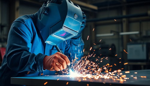
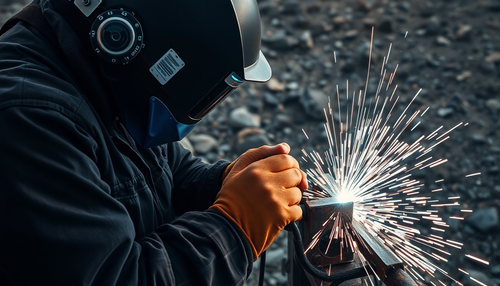
What is seam welding?
Seam welding is a welding method that uses a pair of roller electrodes instead of the cylindrical electrodes used in spot welding. The electrodes move relative to the workpiece, creating a series of overlapping molten cores that form a sealed weld seam.
Seam welding is widely used in welding thin plates of sealed containers to oil drums, cans, radiators, aircraft and automobile fuel tanks, as well as jet, rocket and missile engines.

Seam Welding Electrode
The electrode used for seam welding is a circular roll with a diameter of 50-600mm, with a common diameter of 180-250mm. Roll thickness is 10 to 20 mm.
There are two types of contact surface shapes: cylindrical and spherical, with occasional use of conical surfaces.
In addition to the double-sided chamfer shape, the cylindrical roller can also be transformed into a single-sided chamfer shape to adapt to folded edge seam welding. The width of the contact surface ω varies from 3 to 10 mm depending on the thickness of the workpiece, and the spherical radius R varies from 25 to 200 mm.
Cylindrical rollers are widely used in welding various types of steel and high-temperature alloys, while spherical rollers are commonly used for welding light alloys due to their easy heat dissipation and uniform indentation transition.
Rollers are usually externally cooled during use. When welding non-ferrous metals and stainless steel, clean tap water can be used for cooling. When welding common steel, a water-soluble solution containing 5% borax is commonly used to prevent rust. Internal circulating water cooling is also sometimes used for rollers, especially for aluminum alloy welding machines, but the construction is much more complex.
Seam welding method
Based on the roller rotation and feeding methods, seam welding can be divided into continuous seam welding, intermittent seam welding and step seam welding.
In continuous seam welding, the roller rotates continuously and the current passes continuously through the workpiece. This method easily causes overheating of the workpiece surface and severe electrode wear and is therefore rarely used. However, in high-speed seam welding (4-15m/min), a weld point is formed every half cycle of the 50 Hz AC current, and the zero crossing of the AC current is equivalent to a rest time, which It is similar to that after intermittent seam welding. Therefore, it has been applied in the cylinder and barrel manufacturing industry.
In intermittent seam welding, the roller rotates continuously and the current passes intermittently through the workpiece, forming a seam composed of overlapping fusion cores. Due to the intermittent current, the roller and the workpiece can cool down during the rest time, which can improve the service life of the roller, reduce the width of the heat-affected zone and the deformation of the workpiece, and achieve better welding quality.
This method has been widely used in seam welding of various steels, high temperature alloys and titanium alloys below 1.5mm. However, in intermittent seam welding, the fusion core crystallizes under reduced pressure when the roll leaves the welding area, which can easily cause surface overheating, shrinkage holes and cracks (such as in welding high-temperature alloys). .
Although the molten metal of the last point can fill the shrinkage hole of the previous point when the overlapping amount of the welding point exceeds 50% of the length of the fusion core, the shrinkage hole of the last point is difficult to avoid. However, this problem has been solved by in-house developed microcomputer control boxes, which can gradually reduce the welding current at the beginning and end of the welding seam.
In step seam welding, the roller rotates intermittently and the current passes through the workpiece when it is stationary. Since metal melting and crystallization occur when the roller is stationary, heat dissipation and compression conditions are improved, which can effectively improve the welding quality and extend the service life of the roller. This method is mainly used for seam welding of aluminum and magnesium alloys.
It can also effectively improve the welding quality of high-temperature alloys, but it has not been applied in China because this type of AC welding machine is rare.
When welding hard aluminum and various metals with a thickness of 4+4 mm or more, step seam welding should be used to apply forging pressure to each weld point, such as spot welding, or both hot and cold pulses should be used simultaneously. However, the latter case is rarely used.
According to the type of joint, fillet welding can be divided into lap joint welding, pressure flat joint welding, shim joint welding, copper wire electrode joint welding, etc.
Like spot welding, lap joint welding can be welded with a pair of rolls or with one roll and a center electrode. The minimum joint turn is the same as spot welding.
In addition to the commonly used double-sided seam welding, there are also one-sided single seam welding, one-sided double seam welding and small diameter circumferential seam welding in lap joint welding.
Small diameter circumferential seam welding can be done with
1) roller electrode that deviates from the pressure axis;
2) a positioning device coupled to the cross seam welding machine;
3) a ring-shaped electrode whose workpiece surface is conical and whose tip must fall in the center of the small diameter circumferential weld to prevent the electrode from sliding over the workpiece.
The turn of flat joint welding under pressure is much smaller than that of general seam welding, about 1-1.5 times the thickness of the plate. During welding, the joint is simultaneously flattened, and the thickness of the joint after welding is 1.2-1.5 times the thickness of the plate.
Typically, cylindrical roller faces are used, covering the entire overlapping portion of the joint. To obtain stable welding quality, the overlap must be precisely controlled and the workpiece must be firmly clamped or pre-fixed with a location weld. This method can produce good-looking welds and is commonly used to weld products such as food containers and freezer liners made from low-carbon steel and stainless steel.
Shim joint welding is a method to solve the seam welding of thick plates. Because when the plate thickness reaches 3mm, if conventional lap joint welding is used, slow welding speed, large welding current and electrode pressure are required, which may cause surface overheating and electrode adhesion, making it difficult welding. If shim joint welding is used, these difficulties can be overcome.
Shim joint welding is simply introduced as follows:
First, the edges of the panel parts are joined, and when the joint passes through the roller, two strips of foil are constantly placed between the roller and the panel. The sheet thickness is 0.2-0.3 mm and the width is 4-6 mm. As the foil increases the strength of the welding zone and hinders heat dissipation, it is beneficial for the formation of the molten core.
The advantages of this method are:
- the joint has a relatively smooth reinforcement height;
- good looking;
- regardless of the board thickness, the sheet thickness is the same;
- it is not easy to produce splashes, so the electrode pressure must be the same for a certain current;
- it is not easy to produce splashes, so the electrode pressure can be halved for a certain current;
- and the deformation of the welding zone is small.
Disadvantages are: high joint precision requirements; During welding, the sheet must be placed between the roller and the part, which increases the difficulty of automation.
Copper wire electrode joint welding is an effective method to solve the adhesion of coating to the roller in seam welding of coated steel plates. During welding, round copper wire is fed continuously between the roller and the plate.
The copper wire is spiral shaped and is continuously fed through the roller and then wound onto another spool. The coating only adheres to the copper wire and does not contaminate the roller.
Although copper wire needs to be discarded after use, there is no other seam welding method that can replace it for coated steel plates, especially tinned steel plates. Because the scrap value of copper wire is similar to that of copper wire, the welding cost is not high. This method is mainly used for manufacturing food cans.
Seam Welding Process
The influence of process parameters on the quality of butt welds
The formation of a butt weld joint is essentially the same as that of a spot weld, and therefore the factors that affect the quality of the weld are similar. The main factors include welding current, electrode pressure, welding time, pause time, welding speed and roll diameter.
- Welding current
The heat required to form a molten pool in a butt weld joint is generated by the resistance of the welding area to the flow of current, which is the same as in spot welding. Under certain conditions, the welding current determines the penetration of the fusion and the overlap of the molten pool. For welding low carbon steel, the average melt penetration of the weld pool is 30-70% of the plate thickness, with 45-50% being ideal. To obtain a gas-tight butt weld, the molten pool overlap should not be less than 15-20%.
When the welding current exceeds a certain value, increasing the current will only increase the fusion penetration and molten pool overlap without improving the joint strength, which is not economical. If the current is too high, it may also cause defects such as excessive indentation and burnout.
Due to the significant deviation caused by overlapping weld pools in a butt weld, the welding current is generally increased by 15-40% compared to spot welding.
- Electrode pressure
The effect of electrode pressure on the size of the molten pool in butt welding is the same as in spot welding. Excessive electrode pressure will cause excessive indentation and accelerate roller deformation and wear. Insufficient pressure is prone to porosity and may cause the roller to burn due to excessive contact resistance, shortening its service life.
- Welding time and break time
In butt welding, the size of the molten pool is mainly controlled by the welding time, and the overlap is controlled by the cooling time. At lower welding speeds, a welding time to pause ratio of 1.25:1-2:1 can achieve satisfactory results. When welding speed increases, the distance between welds increases, so the ratio must be increased to obtain the same overlap. Therefore, at higher welding speeds, the ratio of welding time to pause is 3:1 or greater.
- Welding speed
Welding speed is related to the metal to be welded, the thickness of the plate and the strength and quality requirements of the weld. Lower welding speeds are typically used when welding stainless steel, high-temperature alloys, and nonferrous metals to avoid spatter and achieve high-density welds. Sometimes gradual butt welding is used to carry out the entire molten pool formation process while the roll is stopped. The welding speed of this type of butt welding is much lower than that of intermittent butt welding.
The welding speed determines the contact area between the roller and the plate, as well as the contact time between the roller and the heating area, thus affecting the heating and cooling of the joint. When the welding speed increases, the welding current must be increased to obtain sufficient heat. Excessive welding speed can cause burning of the plate surface and electrode adhesion, limiting welding speed even with external water cooling.
Selection of seam welding process parameters
Similar to spot welding, the selection of process parameters for seam welding is mainly based on the properties, thickness, quality requirements of the metal to be welded, as well as the condition of the equipment. Generally, the recommended data can be referenced initially and then adjusted through process experimentation.
The roll size selection principle is consistent with the electrode size selection for spot welding. In order to reduce the edge size, lighten the weight of the structure, improve thermal efficiency and reduce the power of the welding machine, narrow rollers with a contact surface width of 3-5mm have been commonly used in recent years .
Both the diameter of the roller and the radius of curvature of the plate affect the contact area between the roller and the plate, thereby affecting the distribution of the current field and heat dissipation, and causing displacement of the molten core. When the diameter of the roll is different and the thickness of the plate is the same, the molten core will move to the side of the roll with the smaller diameter. When the diameter of the roll and the thickness of the plate are the same, and the plate is curved, the molten core will move to the convex side of the plate towards the electrode.
When seam welding different thicknesses or materials, the direction of displacement of the molten core and the method for correcting the displacement of the molten core are similar to spot welding. Different roller diameters and widths, different roller materials and the use of shims between the roller and plate can be adopted.
When seam welding plates of different thicknesses, a significant deviation occurs in the area of the already welded seam, which can reduce the displacement of the molten core towards the thicker plate. However, when the thickness difference is large, the penetration rate of the thinner plate is still insufficient, and measures must be used to correct the displacement of the molten core. For example, a low-conductivity copper alloy can be used for the roller on one side of the thinner plate, and its width and diameter can be smaller.
Groove weld butt joint design
The design of groove welded butt joints is similar to that of lap joints and spot welding (with the exception of flat groove welding and shim groove welding). Unlike spot welding electrodes, swivel wheels cannot be specially shaped, so the accessibility of the swivel wheel must be taken into consideration when designing slot welding structures.
When welding parts with a small radius of curvature, the decrease in the radius of the inner rotating wheel is limited, which may cause the molten core to move outward and even leave the outer plate unsoldered.
Therefore, it is recommended to avoid designing parts with a very small radius of curvature. In cases where a part has a flat section and a section with a very small radius of curvature, such as a motorcycle fuel tank, increasing the welding current when welding the small radius of curvature can prevent incomplete welds. This is particularly easy to achieve with microcomputer-controlled welding machines.
Welding of Common Metals
Seam welding of low carbon steel
Low carbon steel is the best material for seam welding due to its excellent weldability. For lap seam welding of low carbon steel, high speed, medium speed and low speed schemes can be adopted depending on the purpose and usage.
The welding conditions for lap seam welding of low carbon steel are shown in the table below. When manually moving the workpiece, medium speed is often used to facilitate alignment with the predetermined welding position.
When welding automatically, high or higher speeds can be used if the capacity of the welding machine is sufficient. If the capacity of the welding machine is not sufficient and it is not possible to guarantee high fusion width and depth without reducing the speed, then low speed should be used.
Welding conditions for low carbon steel seam welding
| Plate thickness (mm) | Roll size (mm) | Electrode force(KN) | Minimum overlap(mm) | High speed welding | Medium speed welding | Low speed welding | |||||||||||||
|---|---|---|---|---|---|---|---|---|---|---|---|---|---|---|---|---|---|---|---|
| Minimum B |
Standard B |
Maximum B |
Minimum | standard | Minimum B |
Standard B |
Welding time (week) | Rest time (week) | Welding current (KA) | Welding speed (cm/min) | Welding time (week) | Rest time (week) | Welding current (KA) | Welding speed (cm/min) | Welding time (week) | Rest time (week) | Welding current (KA) | Welding speed (cm/min) | |
| 0.4 0.6 0.8 1.0 1.2 1.6 2.0 2.3 3.2 |
3.7 4.2 4.7 5.1 5.4 6.0 6.6 7.0 8.0 |
5.3 5.9 6.5 7.1 7.7 8.8 10.0 11.0 13.6 |
11 12 13 14 14 16 17 17 20 |
2.0 2.2 2.5 2.8 3.0 3.6 4.1 4.5 5.7 |
2.2 2.8 3.3 4.0 4.7 6.0 7.2 8.0 10 |
7 8 9 10 11 12 13 14 16 |
10 11 12 13 14 16 17 19 20 |
two two two two two 3 3 4 4 |
1 1 1 two two 1 1 two two |
12.0 13.5 15.5 18.0 19.0 21.0 22.0 23.0 27.5 |
280 270 260 250 240 230 220 210 170 |
two two 3 3 4 5 5 7 11 |
two two two 3 3 4 5 6 7 |
9.5 11.5 13.0 14.5 16.0 18.0 19.0 20.0 22.0 |
200 190 180 180 170 150 140 130 110 |
3 3 two two 3 4 6 6 6 |
3 3 4 4 4 4 6 6 6 |
8.5 10.0 11.5 13.0 14.0 15.5 16.5 17.0 20.0 |
120 110 110 100 90 80 70 70 60 |
The following two tables show the welding conditions for continuous electric welding and low carbon steel backing strip welding.
Welding conditions for low carbon steel seam welding
| Plate thickness (mm) | Overlap (mm) | Electrode force(KN) | Welding current(KA) | Welding speed (cm/min) |
| 0.8 1.2 2.0 |
1.2 1.8 2.5 |
4 7 11 |
13 16 19 |
320 200 140 |
Welding conditions for low carbon steel support strip welding
| Plate thickness (mm) | Electrode force(KN) | Welding current(KA) | Welding speed (cm/min) |
| 0.8 1.0 1.2 1.6 2.3 3.2 4.5 |
2.5 2.5 3.0 3.2 3.5 3.9 4.5 |
11.0 11.0 12.0 12.5 12.0 12.5 14.0 |
120 120 120 120 100 70 50 |
Seam welding of quenched and tempered alloy steel
When welding hardened steel alloys, a post-weld heat treatment is also required to eliminate the temper structure, which must be carried out using a double-pulse heating method.
During welding and tempering, the workpiece must not move and must be done on a step welding machine. If this equipment is not available and only an intermittent seam welding machine is available, it is recommended to use a longer welding time and weaker conditions. The following table shows recommended values for welding hardened steel alloys using these conditions.
Welding conditions for low alloy steel seam welding
| Plate thickness (mm) | Roller disc width (mm) | Electrode force(KN) | Time (week) | Welding current(KA) | Welding speed (cm/min) | |
|---|---|---|---|---|---|---|
| Welding | cease | |||||
| 0.8 1.0 1.2 1.5 2.0 2.5 |
5-6 7-8 7-8 7-9 8-9 9-11 |
2.5-3.0 3.0-3.5 3.5-4.0 4.0-5.0 5.5-6.0 6.5-8.0 |
6-7 7-8 8-9 9-10 10-12 12-15 |
3-5 5-7 7-9 8-10 10-13 13-15 |
6-8 10-12 12-15 15-17 17-20 20-24 |
60-80 50-70 50-70 50-60 50-60 50-60 |
Note: The bearing diameter is 150-200mm.
Seam welding of coated steel sheets
Seam welding of galvanized steel sheets
When seam welding galvanized steel plates, attention must be paid to avoid cracking and damaging the tightness of the weld. The reason for cracking is that the zinc that remains in the fusion zone and diffuses into the heat-affected zone makes the joint brittle, which is then subjected to stress. The method to avoid cracking is to select the correct process parameters.
Tests have shown that the lower the weld penetration rate (10-26%), the lower the crack defects. High speed of seam welding can lead to poor heat dissipation, surface overheating and increased fusion depth, which can easily cause cracking. Generally, under the conditions of ensuring the fusion diameter and joint strength, small current, low welding speed and strong external water cooling should be selected as much as possible.
The rollers can easily use the steel wheel transmission to adjust the size and clean the surface of the rollers at any time. The table below shows the welding conditions for seam welding of galvanized steel sheet.
Welding conditions for various types of galvanized steel sheet seam welding
| Coating type and thickness | board thickness (mm) | Roller disc width (mm) | electrode force(KN) | Time (week) | welding current(KA) | Welding speed (cm/min) | |
|---|---|---|---|---|---|---|---|
| Welding | cease | ||||||
| Hot dip galvanized (15-20um) | 0.6 0.8 1.0 1.2 1.6 |
4.5 5.0 5.0 5.5 6.5 |
3.7 4.0 4.3 4.5 5.0 |
3 3 3 4 4 |
two two two two 1 |
16 17 18 19 21 |
250 250 250 230 200 |
| Silver top(2-3um) | 0.6 0.8 1.0 1.2 1.6 |
4.5 5.0 5.0 5.5 6.5 |
3.5 3.7 4.0 4.3 4.5 |
3 3 3 4 4 |
two two two two 1 |
15 16 17 18 19 |
250 250 250 230 200 |
| Calcium Phosphate Treated Anti-Rust Steel Plate | 0.6 0.8 1.0 1.2 1.6 |
4.5 5.0 5.0 5.5 6.5 |
3.7 4.0 4.5 5.0 5.5 |
3 3 3 4 4 |
two two two two 1 |
14 15 16 17 18 |
250 250 250 230 200 |
Seam welding of aluminum coated steel sheets.
The welding conditions for the first type of galvanized steel sheet seam welding are shown in the table below:
Welding conditions for seam welding of aluminum coated steel sheets
| Plate thickness (mm) | Roller disc width (mm) | Electrode force(KN) | Time (week) | Welding current(KA) | Welding speed (cm/min) | ||
|---|---|---|---|---|---|---|---|
| Welding | cease | ||||||
| 0.9 1.2 1.6 |
4.8 5.5 6.5 |
3.8 5.0 6.0 |
two two 3 |
two two two |
20 23 25 |
220 150 130 |
|
For the second type of aluminum coated steel sheet, as well as spot welding, the current should be increased by 15-20%. Due to the more severe adhesion phenomenon than that of galvanized steel sheet, the rollers must undergo regular maintenance.
Seam welding of aluminum coated steel sheets
Aluminum-coated steel sheets are resistant to gasoline corrosion and are therefore often used in automotive fuel tanks. Seam welding of aluminum-coated steel sheets is similar to that of galvanized steel sheets, with the main concern being the issue of cracking. The process parameters can be consulted in the table below:
Welding conditions for galvanized steel sheet seam welding
| Plate thickness (mm) | Roller disc width (mm) | Electrode force(KN) | Time (week) | Welding current(KA) | Welding speed (cm/min) | ||
|---|---|---|---|---|---|---|---|
| Welding | cease | ||||||
| 0.8 | 7 | 3.6-4.5 | 3 5 |
two two |
17 18 |
150 250 |
|
| 1.0 | 7 | 4.2-5.2 | two 5 |
1 1 |
17.5 18.5 |
150 250 |
|
| 1.2 | 7 | 4.5-5.5 | two 4 |
1 1 |
18 19 |
150 250 |
|
Seam welding of stainless steel and high temperature alloys
Stainless steel seam welding is less difficult and is usually done using AC welding. The table below shows the welding conditions for stainless steel seam welding:
Welding Conditions for Seam Welding of Stainless Steel (1Cr18Ni9Ti) (HB/Z78-84)
| Plate thickness (mm) | Roller disc width (mm) | Electrode force(KN) | Time (week) | Welding current(KA) | Welding speed (cm/min) | ||
|---|---|---|---|---|---|---|---|
| Welding | cease | ||||||
| 0.3 0.5 0.8 1.0 1.2 1.5 2.0 |
3-3.5 4.5-5.5 5.0-6.0 5.5-6.5 6.5-7.5 7.0-8.0 7.5-8.5 |
2.5-3.0 3.4-3.8 4.0-5.0 5.0-6.0 5.5-6.2 6.0-7.2 7.0-8.0 |
1-2 1-3 2-5 4-5 4-6 5-7 7-8 |
1-2 2-3 3-4 3-4 3-5 5-7 6-9 |
4.5-5.5 6.0-7.0 7.0-8.0 8.0-9.0 8.5-10 9.0-12 10-13 |
100-150 80-120 60-80 60-70 50-60 40-60 40-50 |
|
During seam welding of high-temperature alloys, due to its high electrical resistivity and repeated heating of the weld, it is more likely to cause segregation of crystals and overheated structures, and even lead to the extrusion of burrs from the surface of the part.
To avoid this, a very slow welding speed and a longer cooling time must be adopted to facilitate heat dissipation. The table below shows the welding conditions for high temperature alloy seam welding:
Welding conditions for seam welding of high temperature alloys (GH33, GH35, GH39, GH44)
| Plate thickness (mm) | Electrode force(KN) | Time (week) | Welding current(KA) | Welding speed (cm/min) | |
|---|---|---|---|---|---|
| Welding | cease | ||||
| 0.3 0.5 0.8 1.0 1.2 1.5 2.0 2.5 3.0 |
4-7 5-8.5 6-10 7-11 8-12 8-13 10-14 11-16 12-17 |
3-5 4-6 5-8 7-9 8-10 10-13 12-16 15-19 18-23 |
2-4 4-7 8-11 12-14 14-16 19-25 24-30 28-34 30-39 |
5-6 5.5-7 6-8.5 6.5-9.5 7-10 8-11.5 9.5-13.5 11-15 12-16 |
60-70 50-70 30-45 30-45 30-40 25-40 20-35 15-30 15-25 |
Seam welding of non-ferrous metals:
Aluminum Alloy Seam Welding
When seam welding aluminum alloys, due to its high electrical conductivity and serious deviation, the welding current needs to be increased by 15-50% compared with spot welding, and the electrode pressure needs to be increased by 10%.
In addition, high-power single-phase AC seam welding machines will seriously affect the balance of three-phase loads in the power grid.
Therefore, domestic aluminum alloy seam welding generally uses three-phase direct current pulse or secondary step-by-step rectifier. The table below shows the welding conditions for welding aluminum alloy using FJ-400 direct current pulsed seam welding machine.
Welding conditions for aluminum alloy seam welding
| Plate thickness (mm) | Spherical radius of the rolling disc (mm) | Step Distance (Point Distance) | LF21、LF3、LF6 | LY12CZ、LC4CS | ||||||
|---|---|---|---|---|---|---|---|---|---|---|
| Electrode force(KN) | Welding time (week) | Welding current (KA) | Points per minute | Electrode pressure (KN) | Welding time (KA) | Welding current (KA) | Points per minute | |||
| 1.0 1.5 2.0 3.0 3.5 |
100 100 150 150 150 |
2.5 2.5 3.8 4.2 4.2 |
3.5 4.2 5.5 7.0 – |
3 5 6 8 – |
49.6 49.6 51.4 60.0 – |
120-150 120-150 100-120 60-80 – |
5.5 8.5 9.0 10 10 |
4 6 6 7 8 |
48 48 51.4 51.4 51.4 |
120-150 100-120 80-100 60-80 60-80 |
In order to increase heat dissipation, aluminum alloy seam welding should preferably use a spherical end face roller and should be externally water-cooled.
Seam welding of copper and copper alloys:
Due to their high electrical and thermal conductivity, copper and copper alloys are almost unsuitable for seam welding. However, for copper alloys with low electrical conductivity such as phosphor bronze, silicon bronze and aluminum bronze, seam welding can be carried out, but a higher current and lower electrode pressure are required than steel. low carbon.
Seam welding of titanium and its alloys
Seam welding of titanium and its alloys is not very difficult, and its welding conditions are approximately similar to stainless steel, but the electrode pressure should be slightly lower.