Copper and copper alloys are widely used due to their unique and superior comprehensive properties. Copper and copper alloys have excellent electrical and thermal conductivity, high oxidation resistance and corrosion resistance in fresh water, salt water, alkaline solutions and organic chemicals.
However, they are susceptible to corrosion in oxidizing acids. Copper alloys have good cold and hot workability and greater resistance. Copper and copper alloys have been widely used in industries such as electrical, electronics, chemical, food, energy, transportation, aerospace and defense.
There are several types of copper and copper alloys produced in industrial production, and most countries classify them based on their chemical composition. Copper and copper alloys can be classified into pure copper, brass, bronze and white copper, among others.
Soft annealed pure copper is generally used for structure welding. Common types of pure copper include T1, T2, T3, T4 and deoxidized copper (oxygen-free copper) TU1, TU2, etc. Brass is a copper alloy composed mainly of zinc.
Commonly used brass and special brass alloys include H62, H68, H96, HPb59-1, HSn62-1, etc. Bronze originally referred to copper-tin alloys, but is now commonly used to describe copper alloys that do not have zinc or nickel as the main alloying element. Common types of bronze include tin bronze (QSn4-3), aluminum bronze (QAl9-2), silicon bronze (QSi3-1), etc.
Additionally, copper alloys with nickel as the primary alloying element are called white copper.
1. Weldability of copper and copper alloys
The weldability of copper and copper alloys is comparatively low, making welding much more challenging compared to low carbon steel. The main difficulties are observed in the following aspects:
(1) Poor weld forming ability:
When welding copper and most copper alloys, difficulties in achieving fusion, incomplete joint penetration, and poor surface formation are likely. This is mainly due to the high thermal conductivity of copper. The thermal conductivity of copper and most copper alloys is 7 to 11 times that of ordinary carbon steel.
As a result, heat is quickly dissipated from the welding zone. The thicker the part, the more severe the heat dissipation. Although copper has a lower melting point and specific heat capacity compared to iron, it is still a challenge to achieve the melting temperature in the welding zone, making it difficult to fuse the base metal and filler metal.
Additionally, copper's excellent thermal conductivity leads to a wider heat-affected zone, which can result in significant deformation when the part has low stiffness. On the other hand, when the stiffness is high, it can cause substantial welding stresses on the workpiece.
Poor surface formation in copper and copper alloys is mainly attributed to the fact that the surface tension during melting is one-third that of steel and the fluidity is 1 to 1.5 times greater than that of steel, making it more susceptible to loss of metal during melting.
Therefore, when welding pure copper and most highly conductive copper alloys, in addition to using high-power, high-energy-density welding methods, it is also necessary to incorporate varying degrees of preheating. It is not permitted to use unilateral welding without support, and when performing unilateral welding, a support plate must be added to control the formation of the weld joint.
(2) High susceptibility to heat cracking in welds and heat-affected zones:
The tendency to thermal cracking in welds is related to the influence of impurities in the weld and is also influenced by the stresses generated during the welding process. Oxygen is a common impurity found in copper and has a significant impact on the tendency of welds to heat crack.
At high temperatures, copper reacts with oxygen in the air to form Cu 2 O. Cu 2 O is soluble in liquid copper but not in solid copper, forming a low-melting eutectic. Impurities such as Bi and Pb in copper and copper alloys have low melting points.
During the weld pool solidification process, they form low-melting eutectics that distribute among dendrites or grain boundaries, causing significant thermal brittleness in copper and copper alloys. When the weld is in the solid-liquid phase, the low-melting point eutectics in the heat-affected zone melt again under the influence of welding stresses, resulting in thermal cracking.
Copper and copper alloys have relatively high linear expansion coefficients and shrinkage rates, and also exhibit strong thermal conductivity. When welding, high-power heat sources are required, resulting in a wider heat-affected zone. As a result, welded joints experience significant internal stresses, which is another factor that leads to cracking in copper and copper alloy welds.
Furthermore, when welding pure copper, the weld metal consists of a single-phase structure. Due to the high thermal conductivity of pure copper, solder tends to form coarse grains. This further aggravates the formation of thermal cracks.
Therefore, to prevent the formation of thermal cracks when using fusion welding to weld copper and copper alloys, the following metallurgical measures must be taken:
1) Strictly control the content of impurities (such as oxygen, bismuth, lead, sulfur, etc.) in copper.
2) Increase the deoxidation ability of the weld by adding alloying elements such as silicon, manganese, phosphorus, etc., to the welding wire.
3) Select welding materials that can obtain a duplex structure, which disturbs the continuity of low-melting point eutectic films and changes the direction of columnar grains.
4) Implement measures such as preheating and slow cooling to reduce welding stresses, minimize root gap size, and increase root pass dimensions to prevent crack formation.
(3) Susceptibility to porosity formation:
When fusion welding copper and copper alloys, the tendency to form porosity is much more significant compared to low carbon steel. To reduce and eliminate porosity in copper welds, the main measures are to reduce the sources of hydrogen and oxygen and preheat to prolong the existence of the molten pool, facilitating the escape of gases.
Use welding wires with strong deoxidizers such as aluminum, titanium, etc. (which can also remove nitrogen and hydrogen) or adding elements such as aluminum and tin to copper alloys can produce good results in terms of deoxidation.
(4) Decrease in welding joint performance:
During the fusion welding process of copper and copper alloys, the welded joints undergo severe grain growth, evaporation and burning of alloying elements, as well as infiltration of impurities, leading to a decrease in mechanical properties, electrical conductivity and resistance to corrosion. corrosion of welded joints.
1) Significant decrease in ductility:
The weld and heat-affected zone exhibit grain thickening, and various low-melting brittle eutectics appear at the grain boundaries, weakening the bond strength of the metal and significantly reducing the ductility and toughness of the joint. For example, when using pure copper welding electrodes for arc welding or submerged arc welding, the elongation of the joint is only about 20% to 50% of that of the base material.
2) Decrease in electrical conductivity:
Adding any element to copper will decrease its electrical conductivity. Therefore, the fusion of impurities and alloy elements during the welding process will, to a certain extent, deteriorate the electrical conductivity of copper joints.
3) Decreased corrosion resistance:
The corrosion resistance of copper alloys is achieved through alloying with elements such as zinc, manganese, nickel, aluminum, etc. The evaporation and oxidation of these elements during the fusion welding process will reduce the corrosion resistance of the joint to a certain extent. The generation of welding stresses also increases the risk of stress corrosion cracking.
Measures to improve joint performance mainly involve controlling the impurity content, reducing alloy burning and carrying out heat treatment to modify the microstructure of the weld. Minimizing heat input during welding and applying stress relief treatment after welding are also beneficial.
2. Selection of Welding Methods
Currently, there are many welding methods available for copper and copper alloys. Commonly used welding methods include gas welding, shielded metal arc welding, tungsten inert gas (TIG) welding, consumable electrode argon arc welding, and submerged arc welding.
The selection of welding methods should be based on the composition, thickness, structural characteristics and performance requirements of the material to be welded.
Copper is the metal with the best thermal conductivity among commonly used welding metals. Therefore, welding of copper and its alloys requires high-power and high-energy-density welding methods.
Higher thermal efficiency and more concentrated energy are preferred. Different thicknesses of materials have different adaptability to various welding methods.
For example, thin plates are more suitable for TIG welding and gas welding. Medium and thick plates are more suitable for submerged arc welding, argon arc welding with consumable electrode and electron beam welding. For thick plates, MIG welding and shielded metal arc welding are recommended.
3. Selection of welding materials
1) Welding wire:
In addition to meeting general process and metallurgical requirements, welding wire for welding copper and copper alloys must mainly control the impurity content and improve the deoxidation ability to prevent the formation of thermal cracks and porosity.
To weld pure copper, deoxidizing elements such as Si, Mn, P are mainly added to the welding wire. Commonly used welding wires include HSCu high purity copper welding wire, which is often used in gas welding together with CJ301 solvent, and submerged arc welding together with HJ431 flux.
2) Welding electrodes:
Arc welding electrodes for copper can be divided into copper and bronze types, with bronze electrodes being most commonly used. Due to the tendency of zinc in brass to evaporate, copper electrodes are rarely used for arc welding.
In these cases, bronze electrodes can be used. Commonly used copper electrodes include T107 pure copper electrode and T207 silicon bronze electrode.
4. Pre-Welding Preparation
The requirements for pretreatment of copper and copper alloy weldments are relatively strict. Pre-welding cleaning of copper and copper alloys mainly involves removing oil and oxide films. Before removing the oxide film, clean the groove and impurities at an interval of 30 mm on both sides of the joint using gasoline or acetone.
Then clean the groove from oil contamination using a 10% sodium hydroxide solution at a temperature of 30-40°C, followed by rinsing with water. Soak the gasket in a 35%-40% nitric acid solution for 2-3 minutes, rinse again with water and dry it.
The removal of oxide films can be done through mechanical and chemical cleaning. For mechanical cleaning, use a pneumatic wire wheel or wire brush to polish the surface of the welding wire and weldment until a metallic shine is visible.
Chemical cleaning involves immersing the solder in a mixed solution of 70mL/L HNO3, 100mL/L H2SO4 and 1mL/L HCl for cleaning, followed by neutralization with an alkaline solution, rinsing with clean water and then air drying warm.
5. Key points of the welding process
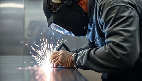
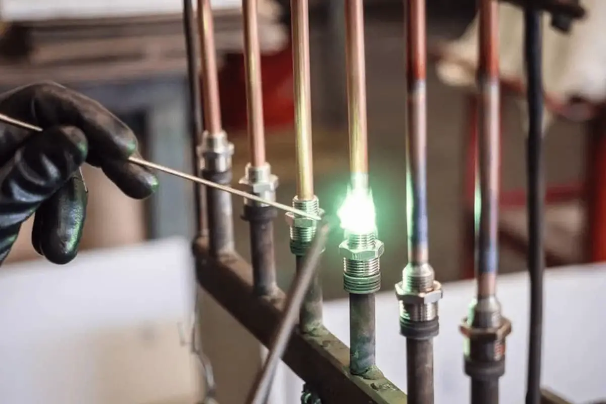
Gas welding:
Gas welding is suitable for welding thin copper parts, repairing copper parts, or welding non-critical structures.
1) Preheating before welding:
Preheating is generally necessary for pure copper gas welding to prevent internal stresses, cracks, porosity, and incomplete penetration from occurring. The preheating temperature for thin plates and small weldments is around 400-500°C, while for thick and large weldments, the preheating temperature should be increased to 600-700°C. The preheating temperature for brass and bronze may be slightly lower.
2) Selection of welding parameters and welding technique: Copper has high thermal conductivity, so the flame energy used for welding is generally 1-2 times that used for welding carbon steel. When soldering pure copper, a neutral flame must be strictly used.
An oxidizing flame can cause oxidation of the weld and burning of alloy elements. A carburizing flame can increase the hydrogen content in the weld and lead to the formation of porosity.
When gas welding thin sheets, the left hand welding method should be used as it helps to suppress grain growth. When the thickness of the part is greater than 6 mm, the right-hand welding method is preferred as it allows higher temperature heating of the base metal and provides better visibility of the weld pool, making the operation more convenient.
The movement of the welding torch should be as fast as possible and each weld seam should not be interrupted randomly. It is preferable to complete each weld seam in a single pass.
When welding long seams, adequate allowance for shrinkage must be left before welding, and positioning must be done before welding. The segmented backlash method should be used during welding to reduce deformation.
For copper welds subject to stress or of greater importance, post-welding joint hammering and heat treatment measures must be taken. After welding thin copper parts, the heat-affected zone on both sides of the weld must be hammered immediately.
For medium thickness boards above 5mm, they should be heated to 500-600°C before hammering. After hammering, the workpiece should be heated to 500-600°C and then quickly cooled in water, which can improve the plasticity and toughness of the joint.
6. Typical examples of welding copper and commonly used copper alloys
There is a water electrode jacket, made of TU1 deoxidized copper. The electrode joint is welded using MIG welding, and the specific welding process is shown in Table 5-37.
Table 5-37 Welding Process Card for TU1 Joint
| Welding process card for joint welding | Number | |||
Joint Diagram: 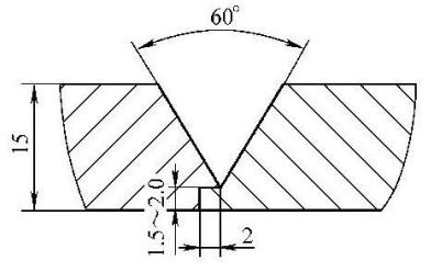
|
Base material | ATU1 | ATU1 | |
| Base material thickness | 15mm | 15mm | ||
| Welding position | Flat welding | |||
| Welding technique | Straight weld path | |||
| Preheating temperature | 500℃ | |||
| Temperature between passes | ≥500℃ | |||
| Nozzle diameter | Φ26mm | |||
| Protective Gas | Air | Gas flow rate (L/min) | Front: 25~30 To go back: |
|
| Welding sequence | |
| 1 | Inspect the groove dimensions and surface quality. |
| two | Remove any oil or dirt from the groove and its surroundings. Clean the grease using 10% NaOH water solution at a temperature of 30~40℃, then rinse with clean water and dry. Remove the oxide film by sanding with a stainless steel wire wheel, then rinse with alkaline water, then rinse with clean water and dry. |
| 3 | Perform spot welding for the first layer using an external placement welding technique. The length should be 100 mm and the distance between the welding points should not exceed 300 mm. If cracks appear in the weld seam, remove them and weld again. |
| 4 | Splice the electrodes into a specially designed fixture. Preheat the workpiece using electric heating, with a preheating temperature of 500°C, and ensure that the temperature of the middle layer is not lower than 500°C. |
| 5 | Start welding from the outside to avoid the formation of weld beads on the inside of the weld seam. Ensure the roundness of the electrode inner circle and the smoothness of the inner surface. |
| 6 | Perform visual inspection. |
| 7 | Straighten if necessary. |
| 8 | Perform post-welding heat treatment. |
Welding Specification Parameters
| Passes | Welding method | Welding Material Grade | Welding material specification | Types of current and polarity | Welding Current (Ampere) | Arc Voltage (Volt) | Welding speed (mm/per pass) | Comments |
| 1~2 | MIG (Semi-automatic) | HSCu | 1.6 | DCEP | 350~400 | 30~35 | 250~300 |