CO2 gas protected welding involves melting the welding wire using welding voltage as the energy source.
The welding wire melts more quickly as the voltage increases.
The welding current is determined by balancing the wire feed speed with the melting speed.
1. Welding current
The selection of welding current should be based on various welding conditions such as plate thickness, welding position, welding speed, material and other relevant parameters.
For protected welding with carbon dioxide gas, it is crucial to ensure that the welding current matches the welding voltage and that the wire feed speed and welding voltage are consistent with the meltability of the welding wire. This is necessary to maintain arc length stability during the welding process.
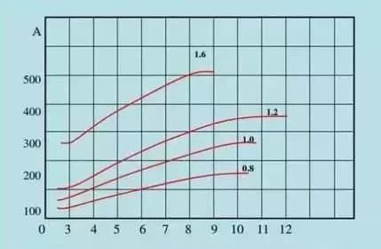
For a given welding wire, increasing the cable size results in a higher wire feed speed.
Likewise, when the current remains constant, using a thinner welding wire will result in a faster wire feed speed.
2. Welding voltage
Welding voltage, also known as arc voltage, is responsible for providing the required welding energy.
Higher arc voltage translates into greater welding energy, faster welding wire melting, and increased welding current.
Arc voltage can be calculated by subtracting the welding circuit loss voltage from the welder output voltage. This can be expressed using the following formula:
you bow = you exit – YOU loss
Assuming the welding machine has been installed in accordance with installation requirements, any loss of voltage is primarily due to cable length.
In situations where welding cables need to be extended, the output voltage of the welding machine can be adjusted according to the table below:
| Welding current Cable length | 100A | 200A | 300A | 400A | 500A |
| 10m | About 1V | About 1.5V | About 1V | About 1.5V | About 2V |
| 15m | About 1V | About 2.5V | About 2V | About 2.5V | About 3V |
| 20m | About 1.5V | About 3V | About 2.5V | About 3V | About 4V |
| 25m | About 2V | About 4V | About 3V | About 4V | About 5V |
3. Welding Voltage Setting
Choose the appropriate welding current based on the plate thickness and welding conditions, and then calculate the welding voltage using the following formula:
<300A: welding voltage=(0.05 × Welding current+14 ± 2) V
> 300A: welding voltage=(0.05 × Welding current+14 ± 3) V
Example 1: If the welding current is 200A, the welding voltage is calculated as follows:
Welding voltage=(0.05×200+14±2)
=(10+14±2)V
=(24±2)V
Example 2: If 400A welding current is selected, the welding voltage is calculated as follows:
Welding voltage=(0.05 × 400+14 ± 3)
=(20+14±3)V
=(34±3)V

4. Influence of welding voltage on welding effect
When the voltage is too high, the arc length increases, leading to larger spatter particles that can easily produce pores. Furthermore, the weld bead becomes wider, while the solution depth and excess height become smaller. This can also result in a “pattern! drum!” sound.
Conversely, when the voltage is too low, spatter increases as the welding wire is inserted into the base metal. Furthermore, the weld bead narrows and both the solution depth and excess height increase. This can lead to a “bang! boom! boom!” sound.