1. Characteristics of the Plasma Arc and its Generator
1. Plasma Arc Formation
A plasma arc is an argon arc with a compressed tungsten electrode with high energy density, temperature and arc strength. The plasma arc is obtained through three compression effects:
1) Mechanical Compression: The restricted expansion of the cross-sectional area of the arc column caused by the opening of the water-cooled copper nozzle is known as mechanical compression.
2) Thermal Compression: The cooling water in the nozzle forms a layer of cold gas near the inner wall of the nozzle, reducing the effective conductive area of the arc column. This further increases the energy density and temperature of the arc column. This effect, achieved through water cooling to further increase the temperature and energy density of the arc column, is known as thermal compression.
3) Electromagnetic Compression: Due to the above-mentioned compression effects, the arc current density increases and the electromagnetic contraction force generated by the arc current's own magnetic field becomes stronger. This results in additional compression of the arc, known as electromagnetic compression.
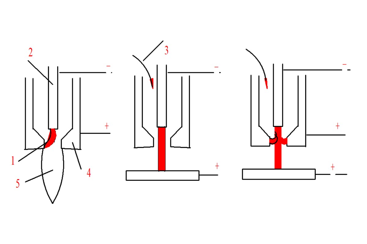
2. Plasma Arc Classification
(1) Arc not transferred
The untransferred arc burns between the tungsten electrode and the nozzle. During welding, the positive pole of the power source is connected to the water-cooled copper nozzle, while the negative pole is connected to the tungsten electrode. The workpiece is not connected to the welding circuit. The arc is created by ejecting plasma gas at high speed. This type of arc is suitable for welding or cutting thinner metals and non-metals.
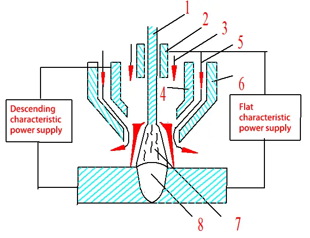
(2) Transferred Arc
The transferred arc burns directly between the tungsten electrode and the workpiece. During welding, the non-transferred arc between the tungsten electrode and the nozzle is first ignited, and then the arc is transferred to the tungsten electrode and the workpiece. The nozzle is not connected to the welding circuit during operation. This type of arc is used for welding thicker metals.
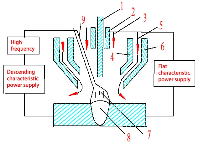
(3) Combined Bow
A combined arc refers to an arc where the transferred arc and the non-transferred arc coexist. The mixed arc can maintain stability at very low currents, making it particularly suitable for welding thin and ultra-thin plates.
Transferred Arc
Combined Bow
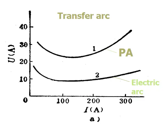
3 . Plasma Arc Characteristics
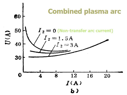
(1) The static characteristic curve of the plasma arc is significantly different from that of the TIG arc:
- 1.1 The E value is greater, thus moving upwards. The straight section becomes narrower and the slope of the rising section increases.
- 1.2 The descending section of the combined arc is not obvious; Therefore, the small current arc is very stable.
(2) The arc temperature is high, ranging from 24,000K to 50,000K, with high power density and energy density of 105-106W/cm2. In contrast, the TIG arc has a temperature range of 10,000-24,000K and a power density of less than 104W/cm2.
(3) The stiffness is high, with a large arc concentration factor.
(4) The heat generated by the arc column has a significant effect on the heating of the workpiece.
4. Characteristics and applications of plasma arc welding
(E) Characteristics
Due to its high energy density, temperature and rigidity, plasma arc has the following advantages compared to conventional arc welding:
1) Strong penetration ability, capable of welding stainless steel plates with a thickness of 8-10mm without the need for chamfer or filler wire.
2) The quality of the weld seam is not sensitive to changes in arc length. This is because the shape of the arch is almost cylindrical and has good straightness. Variation in arc length has minimal impact on the area of the heating point, making it easier to obtain uniform weld bead shapes.
3) The tungsten electrode is embedded in a water-cooled copper nozzle, avoiding contact with the workpiece and preventing the occurrence of tungsten inclusion in the weld metal.
4) The plasma arc has a high degree of ionization, making it stable even at low currents, allowing the welding of miniature precision parts.
The disadvantages of plasma arc welding are as follows:
1) Limited welding thickness, generally below 25mm.
2) The welding gun and control circuits are complex and the nozzle has a short service life.
3) There are multiple welding parameters, requiring a high level of technical proficiency from the welding operator.
(2) Forms
Plasma arc welding can be used to weld various metals that can be welded with tungsten inert gas (TIG) welding, such as stainless steel, aluminum and aluminum alloys, titanium and titanium alloys, nickel, copper and aluminum alloys. Monel. This welding method can be applied in aerospace, aviation, nuclear energy, electronics, shipbuilding and other industrial sectors.
5 . Plasma Arc Generator
1. Classification: Plasma arc welding gun, cutting gun, spray gun.
2. Components
The main components include the electrode, electrode holder, compressed nozzle, intermediate insulator, upper gun body, lower gun body and cooling sleeve. The most critical components are the nozzle and electrode.
1. Mouthpiece
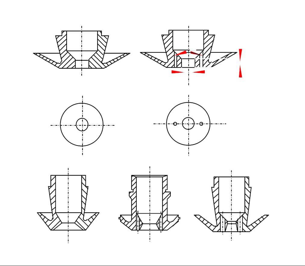
Classification: Based on the number of nozzle holes, there are two types: single hole and multiple hole.
In multi-hole nozzles, in addition to the main central hole, there are several small holes on the left and right sides of the main hole. The plasma gas ejected from these small holes has an additional compressive effect on the plasma arc, causing the cross section of the plasma arc to become elliptical. When the long axis of the ellipse is parallel to the welding direction, it can significantly increase the welding speed and reduce the width of the heat-affected zone.
The most important parameters of the nozzle shape are the compression opening and the length of the compression channel.
1) Nozzle opening (dn):
The dn determines the diameter and energy density of the plasma arc. A smaller diameter results in greater arc compression, but if it is too small, it can lead to decreased plasma arc stability, even causing double arc and nozzle damage. The selection of dn must be based on the welding current, type of plasma gas and flow rate.
2) Nozzle channel length (l0):
Under a given compression gap, a longer l0 provides stronger compression of the plasma arc. However, if l0 is too large, the plasma arc becomes unstable. It is generally necessary for the l0/dn ratio to be within a certain range. For transfer arc, it is generally 1.0-1.2, and for mixed arc, it is 2-6.
3) Conical angle (α):
The conical angle has little impact on plasma arc compression and can vary from 30° to 180°. However, it is preferable to match the shape of the electrode tip to ensure stable anchoring of the anode point on the electrode tip. During welding, the angle is generally 60° to 90°.
Nozzle Material:
The nozzle is typically made of copper and is cooled directly with water.
Electrode:
1) Materials:
Plasma arc welding generally uses thoriated tungsten electrodes or ceriated tungsten electrodes. In some cases, zirconium tungsten electrodes or zirconium electrodes may be used. Tungsten electrodes generally require water cooling. For low current applications, indirect water cooling is used and the tungsten electrode is in the shape of a rod. For high current applications, direct water cooling is used, and the tungsten electrode has an embedded structure.
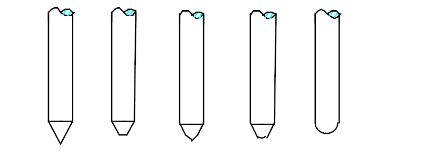
2) Shape:
The tip of a rod-shaped electrode is usually ground into a sharp cone shape or tapered platform shape. For higher current applications, it can also be ground into a spherical shape to reduce burning.
3) Length and concentricity of internal contraction:
Unlike TIG welding, in plasma welding the tungsten electrode is usually contracted within the compressed nozzle. The distance from the outer surface of the nozzle to the tip of the tungsten electrode is known as the internal shrinkage length (lg).
To ensure arc stability and avoid double arc, the tungsten electrode must be concentric with the nozzle, and the internal contraction length (lg) of the tungsten electrode must be appropriate (lg = l0 ± 0.2 mm).
3. Gas delivery methods:
a) Tangential: This method provides high compression, with low pressure in the center and high pressure at the periphery. Helps stabilize the arch in the center.
b) Radial: This method provides less compression compared to the tangential method.
5. Double Arch and its Prevention Measures
1. Double Bow
Under normal conditions, a transferred arc is formed between the tungsten electrode and the workpiece.
However, in certain abnormal situations, a parallel arc, known as a double arc, may occur that burns between the tungsten electrode and the nozzle, as well as between the nozzle and the workpiece.
2. Double arc generation mechanism
Cold gas film breakdown theory
3. Causes and prevention measures for double arc generation
1. Under certain current conditions, the nozzle compression opening is too small or the length of the compression channel is too long, resulting in excessive internal contraction length.
2. Insufficient plasma gas flow.
3. Excessive deviation between the tungsten electrode axis and the nozzle axis.
4. Nozzle blockage due to metal splashes.
5. Incorrect external characteristics of the power supply.
6. Incorrect distance between nozzle and workpiece.
2. Ionic arc welding and cutting.
1. Plasma arc welding process
There are three methods: drilling type, melting type and microbeam plasma arc welding.
(1) Drilling type plasma arc welding
By using a higher welding current and plasma flow, the plasma arc has greater energy density and plasma flow strength. The part is completely melted and forms a small hole that penetrates the part under the action of the plasma flow force, while the molten metal is expelled around the small hole.
As the plasma arc moves in the welding direction, the molten metal moves along the walls of the arc and crystallizes in a weld seam behind the weld pool, while the small hole advances with the plasma arc.
It is suitable for single-sided welding and double-sided forming, and can only be used for single-sided welding and double-sided forming.
When welding thin parts, this can be achieved without chamfering, filler plates or metal filler, achieving double-sided formation in one pass.
The generation of small holes depends on the energy density of the plasma arc. The thicker the board, the higher the energy density required. For thicker sheets, piercing-type plasma arc welding can only be used for the first weld seam.
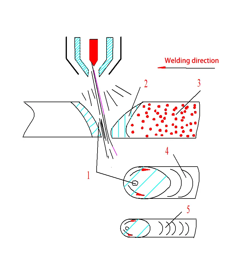
Table 6-1: Applicable thickness for drilling type plasma arc welding
| Material | Stainless steel | Titanium and titanium alloys | Nickel and nickel alloys | Light alloy steel | Low carbon steel |
| Welding Thickness Limit /mm |
8 | 12 | 6 | 7 | 8 |
(2) Fusion-type plasma arc welding
Using a lower plasma gas flow rate, the plasma flow strength is lower and the arc penetration ability is low.
Characteristics:
- It just melts the part and does not form small holes, similar to TIG welding.
- Suitable for welding thin plates, multi-layer overlay welds and corner welds.
(3) Microbeam plasma arc welding
A low current (typically less than 30A) fusion welding process.
Equipment features:
- Small opening compression nozzle (0.6 mm to 1.2 mm).
- Combined bow. The non-transferred arc plays the role of arc initiation and maintenance, ensuring that the transferred arc remains stable even at very low currents (as low as 0.5A).
Process features:
- 1) Can weld thinner metals, with a minimum weldable thickness of 0.01 mm.
- 2) The arc does not reach the equilibrium point with a large variation in arc length and the arc remains columnar.
- 3) Fast welding speed, narrow weld seam, small heat affected zone and minimal welding distortion.
(4) Pulsed plasma arc welding
Uses pulsed current below 15 Hz instead of steady direct current. The arc is more stable, resulting in a smaller heat affected zone (HAZ) and less distortion.
(5) Alternating current plasma welding
It generally uses square wave power supply to weld aluminum alloys.
(6) Transferred plasma arc
In fact, it is a combination of transferred arc and plasma arc, and there are two forms:
2. Welding process and parameters
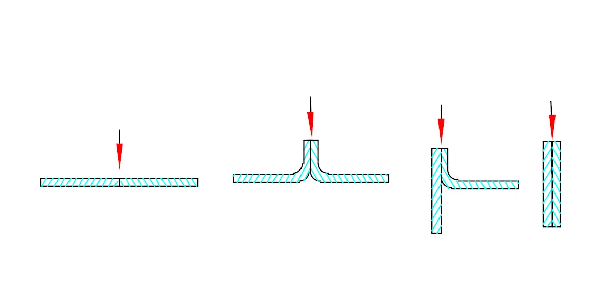
(1) Joint shape and chamfer
The shape of the joint is selected based on the thickness of the board:
- When the thickness is between 0.05 mm and 1.6 mm, the joint shape shown in the figure below is normally used, and welding is done by microbeam plasma arc.
- When the plate thickness is greater than 1.6 mm but less than the material listed in Table 6-4, generally no bevel is made and welding is done using the punching method.
- When the plate thickness is greater than the limit in Table 6-4, a V-shaped or U-shaped chamfer is required for multilayer welding. Compared to TIG welding, smaller chamfers and larger root faces can be used. The maximum value allowed for the root face is equal to the maximum welding thickness for the drilling method. The first layer is welded by punching method and the other layers are welded by fusion method or other welding methods.
(2) Welding current and nozzle opening
Welding current is always selected based on plate thickness or penetration requirements. If the current is too low, the weld may not penetrate and no small holes will be formed. If the welding current is too high, the molten metal may fall out due to the large hole diameter.
The nozzle opening is selected based on the welding current and must be matched appropriately. It is also related to the plasma gas flow rate.
(3) Plasma gas
Plasma gas and shielding gas are generally selected based on the metal to be welded and the magnitude of the current. When using high welding currents in plasma arc welding, it is generally advisable to use the same gas for plasma gas and shielding gas, as using different gases can result in poor arc stability.
Table 6-5 lists typical gases used for high current plasma arc welding of various metals. For low current plasma arc welding, pure argon gas is commonly used as plasma gas. This is because argon gas has a lower ionization voltage, which ensures easy arc ignition.
| Metal | Thickness/mm | Welding technique | |
| Drilling method | Fusion method | ||
| Carbon steel (aluminum tempered steel) | <3.2 | Air | Air |
| >3.2 | Air | 25%Ar+75%He | |
| Light alloy steel | <3.2 | Air | Air |
| >3.2 | Air | 25%Ar+75%He | |
| Stainless steel | <3.2 | Air or 92.5% Ar + 7.5% H 2 | Air |
| >3.2 | Air or 95% Air + 5% H 2 | 25%Ar+75%He | |
| >3.2 | Air or 95% Air + 5% H 2 | 25%Ar+75%He | |
| Reactive metals | <6.4 | Air | Air |
| >6.4 | Air+(50%-70%)He | 25%Ar+75%He | |
The plasma gas flow rate directly determines the plasma flow strength and penetration ability. The greater the plasma gas flow rate, the greater the penetration capacity. However, if the plasma gas flow rate is too high, the diameter of the small hole may become too large, which may affect the weld formation.
Therefore, it is necessary to select an appropriate plasma gas flow rate based on the nozzle diameter, plasma gas type, welding current and welding speed.
When using the fusion method, it is necessary to reduce the plasma gas flow rate appropriately to minimize the force of the plasma flow.
(4) Welding speed
The welding speed must be selected based on the plasma gas flow rate and the welding current, ensuring that all three parameters are adequately combined. When other conditions are constant, increasing the welding speed reduces the heat input and decreases the diameter of the small hole until it disappears.
However, excessively increasing welding speed may result in undercutting or porosity.
On the other hand, if the welding speed is too slow, the base metal may overheat and the molten metal may fall out. Therefore, the welding speed, plasma gas flow rate and welding current must be well matched.
(5) Distance from nozzle to workpiece
If the distance is too great, the penetration capacity decreases. If the distance is too small, it may cause nozzle blockage. Generally, the distance is set between 3 to 8 mm. Compared to tungsten inert gas (TIG) welding, variation in nozzle distance has less impact on welding quality.
(6) Shielding gas flow rate
The shielding gas flow rate must be selected based on the welding current and plasma gas flow rate. Under a certain flow rate of plasma gas, an excessive flow rate of shielding gas may interrupt the gas flow, affecting arc stability and shielding effectiveness.
On the other hand, too low a shielding gas flow rate may result in inadequate protection. Therefore, the shielding gas flow rate must be in an appropriate proportion to the plasma gas flow rate.
For drilling type welding, the shielding gas flow rate is generally in the range of 15 to 30 L/min.
(7) Arc initiation and termination
When using the drilling method to weld thick plates, defects such as porosity and undercutting are likely to occur at the arc initiation and termination points.
For butt joints, arc initiation and termination plates are used. The arc is first started at the initiation plate, then transferred to the workpiece, and finally terminated at the termination plate, closing the small hole.
However, for circumferential joints, arc initiation and termination plates cannot be used. Instead, a method of gradually increasing the welding current and plasma gas flow rate is used to initiate the arc on the workpiece, and the arc is closed by gradually reducing the current and plasma gas flow rate to close the small hole.
2. Plasma arc cutting
1. Cutting principle
Melting and blowing principle: The plasma arc completely melts the workpiece, and the high-speed mechanical washing force of the plasma flow blows away the molten metal or non-metal, forming a narrow cut.
Gas cutting: Uses combustion and blowing.
Benefits:
- 1. Can cut any metal: steel, aluminum, tungsten, copper, titanium, molybdenum, etc. Can cut non-metals: such as granite, refractory bricks, concrete, etc.
- 2. Fast cutting speed and high productivity.
- 3. Good cutting quality: small and smooth heat affected zone (HAZ), minimal deformation, and the cutting is almost vertical.
Disadvantages:
- Equipment load, high voltage without load.
2. Cutting techniques
1. Plasma Gas
1) Types
- Argon gas: Low no-load voltage (70-80V) but low arc temperature, suitable for cutting thicknesses less than 30mm.
- Nitrogen gas: Due to the endothermic decomposition of nitrogen gas, the arc is further compressed, resulting in a higher arc temperature and greater heat transport capacity, allowing for greater thickness and cutting speed. No-load voltage greater than 165V.
- Nitrogen gas + hydrogen gas: Further increases the arc temperature and heat transport capacity, allowing greater thickness and cutting speed. No-load voltage greater than 300V.
- Nitrogen gas + argon gas
- Air: Low cost, high arc temperature due to exothermic oxidation reactions, allowing large cutting thicknesses and high cutting speeds. The cutting quality is also good, but the tungsten electrode is prone to oxidation. Therefore, hafnium-copper electrodes or zirconium-copper composite electrodes are often used, as they form an oxide film that prevents further oxidation.
2) Flow rate
The plasma gas flow rate is much greater than that used in welding, as the plasma arc requires a harder arc.
2. Process Parameters
1) No-load voltage:
It not only affects the arc ignition performance, but also influences the arc stiffness. Higher no-load voltage results in a stronger arc and greater discharge force, allowing for greater cutting speed and thickness.
2) Arc current and voltage:
Increasing arc current and voltage can increase thickness and cutting speed, with voltage having a more significant effect. However, increasing the current can lead to the formation of a double arc and a larger cut-off.
3) Cutting speed:
It is recommended to maximize speed by ensuring complete penetration. Increasing cutting speed improves productivity and reduces deformation and heat affected zone. Slow cutting speeds result in lower productivity, greater risk of slag formation and greater heat affected zone.
4) Distance from nozzle to part:
Generally, a distance of 8-10 mm is preferred. Increasing the distance increases arc power, but also leads to greater heat dissipation, lower arc efficiency, reduced discharge force, and increased risk of slag formation. It is also more prone to double arches. On the other hand, too low a distance may result in nozzle blockage.