The electro-hydraulic synchronization system of the CNC press brake is composed of the following eight components:
- Unit Assembly
- Pressure Control Valve Unit
- Closed Loop Control Valve Unit
- Closed-Loop Proportional Valve Amplifier
- Hydraulic cylinder
- Position Detection System
- CNC system
- Electrical System, etc.
The synchronization of the position of the two piston cylinders during the stroke and the positioning of the stroke end point are achieved by the electro-hydraulic synchronous servo system, which has high synchronization and repeated positioning accuracy. Refer to the figure below to see the working principle of the press brake synchronization system.
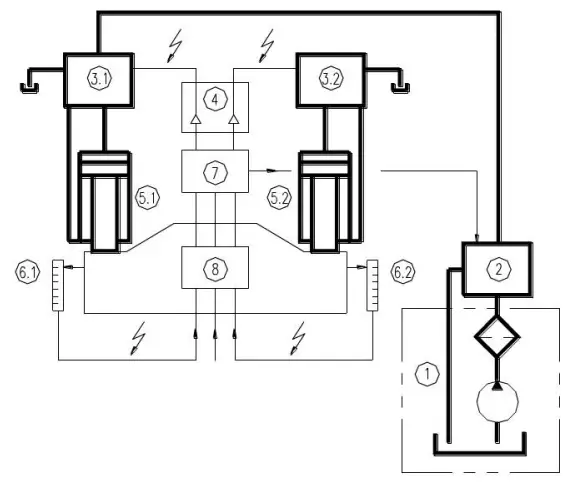
Fig.2 Schematic diagram of synchronous control
The oil outlet from the drive assembly enters the hydraulic cylinders on both sides through the pressure control valve unit and the closed-loop control valve unit, causes the ram to move down (or up) and is detected and sent back to the CNC system and the electrical system through the position detection system at both ends of the ram. Then the CNC system supplies the processing signal to the closed-loop proportional valve amplifier, and the closed-loop control valve unit distributes the oil to the hydraulic cylinders at both ends to achieve synchronization at both ends of the ram . It has high synchronization and repeated positioning accuracy.
Refer to the hydraulic schematic diagram of the CNC press brake (Fig. 3) and the action sequence table attached in the upper right corner for the principle of the hydraulic system and the action sequence of the hydraulic components of the CNC press brake.
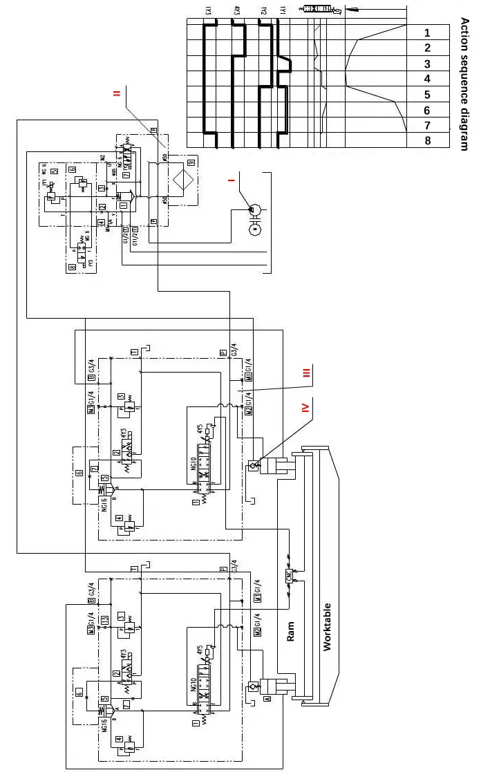
Fig.3 Hydraulic schematic diagram of CNC press brake
See Figure 4 for hydraulic system pressure control valve group layout and Figure 5 for closed loop control valve group layout. The serial number and component code in the figures are the same as in Figure 3.
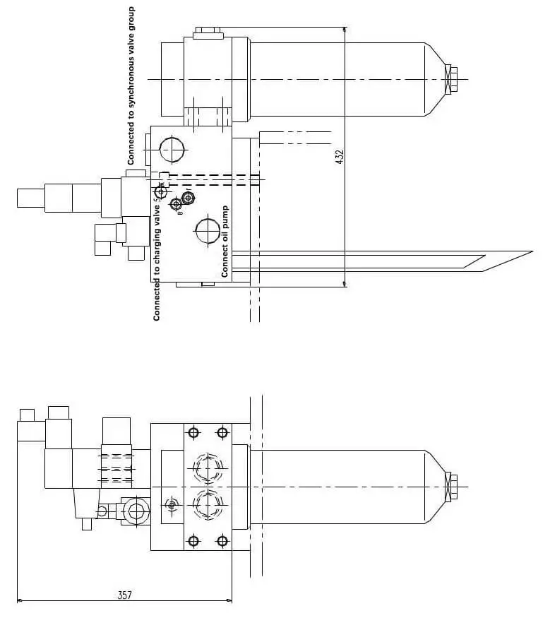
Figure 4. Hydraulic system pressure control valve group
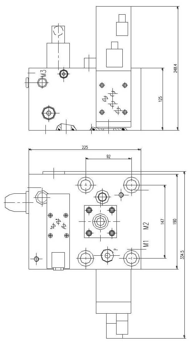
Fig.5 group of closed loop control valves
During machine operation, the ram must pass through eight stages to complete a stroke:
- Fast descent
- Slow down
- Press and hold pressure
- Pressure relief
- Fast up
- Slow down
- Slow to neutral
- Stop at top dead center.
Phase 1:
To turn on 4Y3 and 4Y5, press the down button.
When 4Y3 is turned on, port A and port T of lift valve (III-2) are connected, port P is closed, so the upper chamber of cartridge valve (III-5) is connected to the fuel tank. oil and cartridge valve (III-5) is open. When 4Y5 is turned on, ports P and B of the proportional servo valve (III-1) are connected, ports A and T are connected, and the throttle port is adjusted to maximum.
Due to the opening of valve (III-5), the oil in the lower chamber of the two oil cylinders quickly returns to the oil tank through ports A and T of valve (III-5) and valve (III-1), and the oil pressure necessary to support the ram is lost.
As a result of the self-weight of the ram, the piston falls quickly, and the volume change rate of the upper chamber of the oil cylinder is greater than the flow of the oil pump, causing the upper chamber of the oil cylinder to generate negative pressure, and the oil in the oil tank is pressed into the upper chambers of the two oil cylinders through the filling valve (IV). The ram moves quickly downward without load.
Level 2:
When the ram quickly reaches the set value, provide the 4Y5 with a new parameter value through the CNC system to reduce the throttle port of the proportional servo valve (III-1) and slow down the ram.
Phase 3:
Increased work progress:
4Y3 is off, 1Y2 is on, 4Y5 is on and the proportional servo valve (III-1) is connected to ports PB and AT.
As 4Y3 loses power, the lift valve (III-2) is reset (PA port is connected and T port is closed), then valve (III-5) is also closed, the oil circuit in the chamber bottom of the oil cylinder is cut off and the pressure required to support the ram is quickly generated, preventing the ram from falling freely.
1Y2 is turned on, connecting the PA port and the BT port of the reversing valve (II-7). Close the charge valve control port, close the charge valve, and cut off the passage between the upper chamber of the oil cylinder and the oil tank.
The oil outlet from the oil pump enters the upper chamber of the oil cylinder through the fine oil filter (II-9) and the PB port of the proportional servo valve (III-1). The proportional overflow valve (II-5) establishes pressure through the 1Y1 electromagnet, forcing the ram to move downward against the supporting force and the pressing force of the oil cylinder lower chamber material, while the oil in the chamber bottom of the oil cylinder returns to the oil tank through the PA port of the relief valve (II-5) and the AT port of the proportional servo valve (III-1).
This completes the pressing and reinforcing process.
Phase 4:
When pressing is complete, 1Y2 remains on, 1Y1 loses power, and 4Y5 turns on.
As 1Y1 turns off, the system oil begins to relieve pressure as 4Y5 turns on. Ports P, A, B and T of the proportional servo valve (III-1) are closed to achieve balance of forces of the upper and lower cavities of the oil cylinder.
Phase 5:
After pressure relief, 1Y2 is turned off and 1Y1 and 4Y5 are turned on.
As 1Y2 is de-energized, the directional valve (II-7) is reset, connecting the PB port and the AT port. As the PB port is connected, the charging valve (IV) is opened to connect the oil return path between the upper chamber of the oil cylinder and the oil tank. 4Y5 is energized and the PA port and BT port of the proportional servo valve (III-1) are connected.
At this time, the oil outlet from the oil pump flows into the lower chamber of the oil cylinder through the fine filter (II-9), PA port of the proportional servo valve (III-1), the one-way valve (IV-11), and valve (III-5), and proportional overflow valve (II-5) establish pressure across electromagnet 1Y1, causing the ram to move rapidly upward. The hydraulic oil in the upper chamber of the oil cylinder returns to the oil tank through the charging valve (IV).
Phase 6 and 7:
As the ram rises to a certain position, 1Y1 continues to turn on while changing the electrical signal of 4Y5 to adjust the opening of the proportional servo valve (III-1) and close it slowly to slow the rise and reach top dead center .
Phase 8:
When the ram reaches top dead center, 1Y1 loses power and the ram stops working, completing one full stroke of the machine tool.
The synchronous servo system of a press brake controls the ram of the CNC press brake to always remain parallel to the workbench during rapid approach, work stroke, end point positioning, and return.
If the ram tilts due to various disturbances and eccentric loads, the position detection system at both ends of the ram detects and feeds the deviation value back to the computer, which adjusts parameters such as the flow and pressure of the oil entering the cylinder. of oil through the proportional servo valve to keep the positions of the two pistons synchronized, ensuring that the ram remains parallel to the bench.