Basics of the press brake hydraulic system
Hydraulic system composition
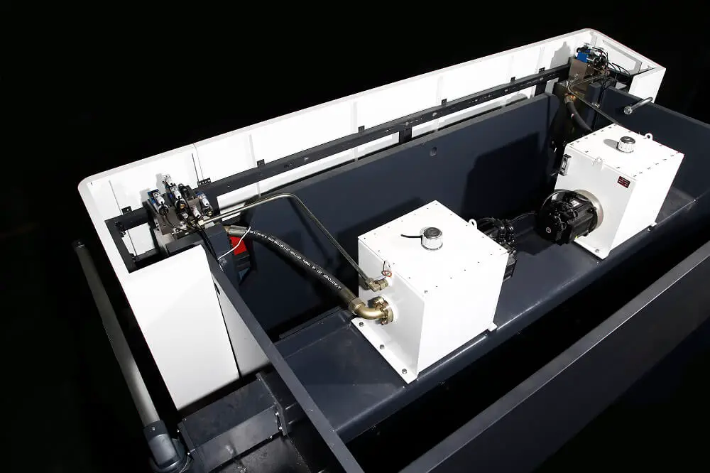
Electric power plant
Hydraulic Pump: The mechanical energy supplied by the main engine is converted into liquid pressure energy, which serves as a power supply device for the system.
actuator
Hydraulic Cylinder (or Motor): Converts the energy of fluid pressure into mechanical energy and performs work on the load.
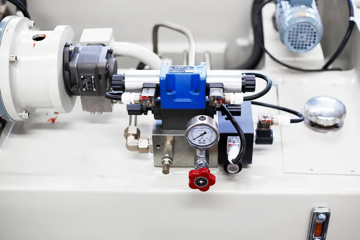
Control device
Various hydraulic control valves are used to control the direction, pressure and flow of fluid to ensure that the actuator completes its intended work task.
Auxiliary equipment
The fuel tank, oil pipes, oil filters, pressure gauges, coolers, water separators, oil mixers, mufflers, pipe fittings, pipe joints and various signal converters create the necessary conditions to ensure the normal operation of the system .
Working environment
Hydraulic oil or compressed air as a carrier to transfer motion and power.
Oil tank
The function of the fuel tank:
- Hold the reserved oil.
- Heat dissipation.
- Separate the air from the oil.
- Precipitation of pollutants.
- Condensate separation
Fuel tank structure:
Fuel tank size (volume) – V = 3-5q for fixed equipment; V≈1q for hiking equipment.
The unit of V is liter and the unit of q is liter/minute.
When designing the fuel tank, there should be 10-15% space at the top of the fuel tank, mainly considering factors such as changes in liquid level and foam.
The effective volume of the fuel tank should be 6 to 12 times the total flow of the hydraulic system oil pump.
The oil temperature is recommended between 30-50°C, with a maximum temperature not exceeding 65°C and a minimum temperature not lower than 15°C.
The bulkhead should be designed into the fuel tank, and the distance between the oil suction area and the oil return area should be as large as possible.
Hydraulic oil
It is very important for the perfect functioning, operational reliability, useful life and economy of the hydraulic system.
- Power transmission from the hydraulic pump to the hydraulic motor or cylinder
- Lubrication of moving parts
- Protect metal surfaces immersed in oil
- Remove dust, impurities, water, air, etc.
- Cooling
The important concept of oil
- High cleanliness = high reliability
- New oil is dirty oil
- Oil usage time: 2,000-4,000h
Cleaning
Viscosity standard: The viscosity value is always related to a certain temperature. The viscosity value decreases as the temperature increases and increases as the hydraulic oil pressure increases. The viscosity standard is ISO standard at 40℃, which can be divided into #10, #22, #32, #46, #68, #100 hydraulic oil.
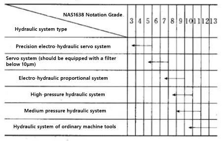
Oil pollution grade standards: International ISO-4406 and American NAS-1638. At the NAS9 level, the hydraulic system generally does not fail. When the pollution level drops to the NAS10-11 level, the hydraulic system occasionally fails. When the degree of oil pollution drops below the NAS12 level, failures often occur. At this time, the hydraulic oil must be circulated and filtered.
Commonly used hydraulic valves
Classification
According to function it can be divided into:
- steering valve
- flow valve
- pressure valve
According to installation method can be divided into:
- plate valve
- stack valve
- bidirectional cartridge valve
- threaded cartridge valve
According to control method can be divided into:
- pneumatic operated valve
- hydraulic valve
- motorized valve
- solenoid valve
- proportional valve
- proportional servo valve
- servo valve
Directional valve
The basic function of the directional valve is to facilitate communication and cut-off between two different hydraulic circuits, or to control the starting, stopping and movement direction of the actuator (cylinder or motor) as necessary.
Classification of directional control valves
Divided by control method:
- Solenoid valve
- Manual directional valve
- Hydraulic directional valve
- Motorized directional valve
- Pneumatically actuated valve
Divided by installation method:
- Disc valve
- In-line valve
- Threaded Cartridge Valve
Exhaust valve
Characteristics
The most important function of the relief valve is to limit system pressure, thus protecting various components and pipes and avoiding the danger of overload and ruptures.
This valve is therefore also called a pressure valve or safety valve.
When the system pressure reaches the defined pressure value, the relief valve starts to act as a pressure limiter.
The originally closed valve is now opened and excess flow flows back into the tank through the valve port.
When working in this way, the relief valve is installed on the bypass.
It should be noted that the power loss of flow Q with pressure P passing through the relief valve is P×Q/612.
The lost energy is transmitted to the hydraulic system, which causes the hydraulic oil temperature to increase.
Fundamental
The input pressure P acts on the measuring area A and the resulting hydraulic pressure is compared with the spring force.
If the hydraulic pressure exceeds the set force of the spring, the valve core compresses the spring and the valve port opens, connecting the path between the valve inlet and outlet.
Flow valve
The flow valve controls the speed of the hydraulic actuator.
This is achieved by changing the size of the cross-sectional area of the accelerator to change the volume flow rate Q of the actuator.
The flow valve can be divided into butterfly valve and speed control valve.
Retention valve
The function of the check valve is to cut off flow in one direction and allow flow in the other direction to pass without restriction.
One-way valve sealing elements have spherical, conical valve or plate valve shapes.
The relatively weak spring force needs to be overcome when the sealing element is opened.
These basic principles are directly reflected in graphic symbols.
Bidirectional Cartridge Valve
The two-way cartridge valve is designed as a plug-in structure and installed in a compact control circuit.
In most cases, the cover plate also functions as a connecting block between the main valve and the pilot valve.
By controlling the main valve with a suitable pilot valve, pressure, reversing or throttling functions, or a combination of these functions, can be achieved.
Functions include directional control, overflow control, decompression control and sequence control.
Proportional valve
Open circuit proportional valve – electro-hydraulic proportional valve
- proportional relief valve
- proportional pressure reducing valve
- proportional throttle valve
- proportional flow valve
- proportional directional valve
Closed Loop Proportional Valve – Servo Proportional Valve
- The amplifier has integrated servo proportional valve NG6, NG10, NG16, NG25, NG32
- NG6 ~ NG50 Amplifier External Proportional Servo Valve
Proportional servo valve
Frequency response: 120Hz
Hysteresis: 0.1%
No dead zone (zero coverage)
Automatic compensation without balancing valve
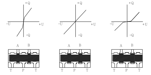
Open Loop Control System:
If there is no feedback between the output and input of the system, which means that the output of the control system does not affect the control of the system, such a system is called an open-loop control system.
Closed-loop control system:
Closed-loop control system is an automatic control system based on the feedback principle.
The feedback principle means controlling according to the system output change information. That is, comparing the deviation between the system behavior (output) and the expected behavior and eliminating the deviation to obtain the expected system performance.
In the feedback control system, there is a direct signal path from input to output and a feedback signal path from output to input.
The two form a closed circuit.
Therefore, the feedback control system is also called a closed-loop control system.
The open-loop control system has a simple structure and is relatively economical.
The disadvantage is that the error caused by interference cannot be eliminated.
Compared with the open-loop control system, the closed-loop control system has a series of advantages.
In the feedback control system, no matter the reason (external disturbance or internal system change), a corresponding control effect will be generated to eliminate the deviation as long as the controlled quantity deviates from the specified value.
Therefore, it has the ability to suppress interference, is insensitive to changes in component characteristics, and can improve system response characteristics.
However, introducing a feedback loop increases system complexity and inappropriate gain selection can cause system instability.
To improve control accuracy, disturbance control (i.e., feedforward control) is often used as a complement to feedback control to form a composite control system when the disturbance variable can be measured.
| Open circuit proportional valve | Closed circuit servo valve |
| Frequency response: 15Hz | Frequency response: 120Hz |
| Hysteresis: 5% | Hysteresis: 0.1% |
| Reverse error: 1% | Reverse error: 0.05% |
| Repetition accuracy: 0.1 | Repetition accuracy: 0.01 |
| Median dead zone | Zero coverage |
Hydraulic system principle of electro-hydraulic servo press brake
Principle of Electro-Hydraulic Synchronous Press brake (Take the system below 300 tons as an example)
Pressure control
Start the oil pump motor. According to the required bending force, the proportional pressure valve (4) controls the two-way cartridge valve (2) to adjust the pressure of the hydraulic system to meet the bending force requirements.
The pressure valve (4.1) is a safety valve that controls the maximum system pressure.
Duty cycle
Come down
Apply a 1Y1 voltage (20%~30%) to the proportional pressure valve (4) and the 1Y2 solenoid valve (6) loses power. When solenoid valve (5) 4Y3 is energized, it supplies a positive voltage to the proportional servo valve.
As the weight of the slider decreases rapidly, the oil is sucked into the upper cylinder cavity through the flow valve, and the oil discharged from the oil pump enters the upper cylinder cavity through the proportional servo valve (2).
The oil from the cylinder's lower chamber is returned to the tank through the solenoid valve 5 (AP) and the proportional servo valve (2) (B → T).
The fast descending speed of the slider can be obtained by adjusting the control voltage of the 4Y5 proportional servo valve to control the opening of the proportional servo valve to obtain different speeds.
Work progress
The proportional pressure valve (4) 1Y1 is energized, the electromagnetic reversing valve (6) 1Y2 is energized, the filling valve is closed, the solenoid valve (5) 4Y3 is de-energized, and the pressurized oil discharged from the oil pump passes through the proportional servo valve (2) and enters the upper cylinder cavity (without rod cavity).
Oil in the cylinder's lower chamber returns to the oil tank through the back pressure valve (4) and proportional servo valve (2) while the slider is depressed.
By adjusting the control voltage 4Y5 of the proportional servo valve, different working speeds are obtained by controlling the opening of the proportional servo valve.
The safety valve (3) prevents the pressure in the lower cavity of the oil cylinder from becoming too high and the setting pressure from being 10% higher than the system pressure.
The setting pressure of the backpressure valve (4) is generally the equilibrium pressure plus (30 ~ 50) bar.
Keep the pressure
When the ram reaches bottom dead center, the proportional servo valve 2 (4Y5) is 0V to cut off the path of the upper and lower chambers of the cylinder, and the slider stops at bottom dead center.
Downloading
After the pressure maintenance of the press brake is completed, the proportional pressure valve maintains the pressure, and the system supplies the proportional servo valve 2 (4Y5) with a certain negative voltage, so that the proportional valve is slightly opened (return direction) .
At the same time, the ram will also move up a little, and the value is set by the discharge distance parameter.
The time required for the unloading process is defined by the decompression speed parameter.
The pressure in the upper cavity of the cylinder is released through the proportional servo valve (2).
Turn back
When the solenoid valve (6) 1Y2 loses power, a certain voltage is applied to the proportional pressure valve (4), the solenoid valve (5) 4Y3 loses power, and the proportional servo valve (4Y5) has a negative voltage.
Pressurized oil passes from the pump block through 2 timing blocks.
Hydraulic oil is directed from the upper proportional servo valve (2) and the electromagnetic reversing valve (5) (PA) to the lower cylinder chamber (with rod chamber) and to the upper cylinder chamber (without rod chamber) it is returned to the tank through the filling valve.
The ram returns quickly.
The return speed can be obtained by adjusting the control voltage of the 4Y5 proportional servo valve to control the opening of the proportional servo valve (2) to obtain different speeds.
Bench compensation
Bench compensation is achieved by controlling the proportional pressure reducing valve (10) 1Y3.
The pressurized oil enters the compensation cylinder through the proportional pressure reducing valve (10), and the pressure of the proportional pressure reducing valve is adjusted by changing the voltage of the proportional pressure reducing valve (10).
This is done to make the table convex and compensate for the deformation of the table during bending.
Troubleshooting hydraulic system of electro-hydraulic servo press brake
Pressureless system
Check whether the proportional pressure valve plug (04) is loose, whether there is a corresponding electrical signal in 1YI and whether the safety valve (4.1) is loose.
Check whether the bidirectional cartridge valve spool (02) is stuck and whether the fluid resistance (09) installed on the spool is blocked. Also check whether the pressure proportional valve spool (04) is stuck.
Open the fuel tank cap and check the oil return condition of the oil return port if the set pressure cannot be reached. If there is no oil return or the oil return flow is not urgent, the oil pump is damaged and needs to be replaced.
Crash below
First, check whether the pressure in the back pressure valve and safety valve has decreased.
Stop the ram at the upper starting point and remove the proportional servo valve in the timing block. Observe whether there is any oil overflow at port A of the proportional servo valve in the valve block. If the oil overflows, the timing block is leaking. Otherwise, there is a cylinder leak. Alternatively, reverse the left and right sync blocks. If the sliding phenomenon does not follow the timing blocks, there is a cylinder leak.
Clean the back pressure valve spool. If the problem persists, clean the seat valve and safety valve.
If the ram slips in one section and not in other sections, this is because the cylinder is not sealed well in one section.
The beating is not fast, the rapid deceleration is slow, and the rapid deceleration is not synchronized.
Check whether the seat valve plug in the timing block is loose and whether there is a corresponding electrical signal. Verify that the proportional servo valve activation signal is provided and that the feedback is consistent. If not, it means that the proportional servo valve spool is stuck and must be cleaned.
Check that fluid resistance 6 in port X of the timing block is blocked and check that the fill valve under the timing block is stuck.
Check whether the ram rail or cylinder is too tight.
The beating is in rapid downwards, but without progress
In the diagnostic state, supply the corresponding electrical signals to the proportional servo valve (2), the proportional pressure valve (04) and the electromagnetic directional valve (06). Close the filling valve and adjust the corresponding opening direction of the proportional servo valve. If the cylinders on both sides cannot be activated, check whether the 1Y2 plug of the electromagnetic reversing valve (06) on the pump block is loose, whether there is a corresponding electrical signal and whether the valve core is stuck. If a particular cylinder cannot be actuated, check whether the fluid resistance (6) in the cylinder timing block is blocked and whether the fill valve under the timing block is stuck.
The beat quickly descends and enters the middle pause
- If the liquid level in the fuel tank is too low, which causes the fill valve to take in air;
- The oil inlet of the filling valve is not sealed and leaks air;
- The filling valve spring is broken.
The beating cannot return or the return speed is too slow
In the diagnostic state, check whether there is pressure in the hydraulic system.
In the diagnostic state, supply the corresponding electrical signals to the proportional servo valve, proportional pressure valve and electromagnetic directional valve simultaneously. Open the filling valve and adjust the corresponding opening direction of the proportional servo valve. For example, if the cylinders on both sides cannot return normally and quickly, check whether the electromagnetic directional valve on the pump block has the corresponding electrical signal and whether the valve core is stuck. If a cylinder cannot return normally and quickly, check whether the fluid resistance in the cylinder timing block is blocked and whether the fill valve under the timing block is stuck.
Check whether the proportional servo valve startup signal is consistent with the feedback. If not, it means that the proportional servo valve spool is stuck and needs to be cleaned.
The oil temperature rises too quickly, the system pressure is too high when the oil pump is running dry, and the engine is easy to trip
When the oil pump is running dry, the system pressure is generally about 1 MPa. If the pressure is too high, check whether the fluid resistance (8) of port Y on the pressure control cover is blocked.
When the machine's oil pump is dry, there is no pressure in the system, but the oil temperature rises quickly. Pollutants in the oil, oil tank or piping can block the filter element and the oil filter element needs to be replaced.
Check whether the working distance is too long or the waiting time is too long.
Check whether the piping configuration of the machine tool hydraulic system is reasonable.
Debugging hydraulic system controlled by electro-hydraulic servo pump press brake
First boot
Exhaust
Completely release the safety valve (014) on the cylinder's upper valve group. Then, enter the DELEM system diagnostic interface and move the valve by approximately 40%. The corresponding speed should be about 700 revolutions and the torque setting value should be about 80DA. Set each run for 5 to 10 minutes and close the safety valve.
Precautions
When closing the safety valve, a pressure gauge must be used to adjust the pressure in the lower chamber to 20 MPa. If a pressure gauge is not available, fully tighten the safety valve and loosen it once. After exhaustion is complete, noise may occur in the first few actions and the return stroke may not occur. Timing and slow return problems are caused by air in the machine's piping and cylinder that has not been completely exhausted.
Generally, the machine will work normally after 5-8 cycles. If the exhaust of the machine tool is completed and it still cannot return, the lower chamber safety valve must be released for exhaust according to the above operation. Do not use automatic parameter search repeatedly or complete the return stroke by force to avoid damage to the oil pump.
During initial commissioning, the speed of the quick return stroke must be controlled within 100 mm/s to avoid damage to the oil pump due to lack of air discharge and high speed.
Pressure adjustment
Bottom cavity safety valve: The factory setting of the bottom cavity safety valve is 20MPa and does not need to be adjusted if not necessary.
Backpressure valve adjustment: First, observe the static backpressure of the machine, which is generally around 4-5 MPa, and then add 3-4 MPa to this value as the dynamic backpressure of the machine.
The back pressure valve can be adjusted according to the actual working conditions of the machine.
Slide the beat to the bottom
Enter the DELEM diagnostic interface, shift the two valves by 20%, set the DA value of the pressure valve (torque) to about 80DA, and then open the quick release valve. The ram will slowly fall until it reaches the lower mold.
Precautions
The setting pressures of the back pressure valves on both sides should be basically the same. Excessive errors will cause problems such as asynchronous work.
When sliding the ram all the way in, be sure to apply torque; otherwise, the ram will fall quickly and hit the mold or the bottom of the cylinder, which may cause unpredictable danger.
Advantages of electro-hydraulic servo bending machine
Significant energy savings, greater efficiency and 70% reduction in energy consumption.
Use pump control instead of conventional valve control to eliminate throttling losses.
Optimize the precise distribution of the required amount of oil by dynamically adjusting the servo motor speed.
Less useless energy consumption: turn off the engine when no flow or pressure is needed.
Positive impact on the environment and reduced usage costs.
Reduction in energy consumption and CO2 emissions.
Reduced installation capacity: the servo motor can be significantly overloaded in a short time and the actual installation power is only 50% of the theoretical installation power.
Reduce fuel tank volume by 50% and use less hydraulic oil.
Low thermal equilibrium temperature, no cooling device required, and long service life of hydraulic components.
Noise reduction: significant reduction in noise in idling, deceleration, pressure retention and return conditions, improving the working environment.
Greater security and savings.
The servo motor brakes faster than ordinary motors and pressure and flow are quickly cut off in emergency situations.
Reduced sensitivity to oil particles from NS7 (proportional servo valve) to NS9 (plunger pump), temperature sensitivity is reduced, operating temperature of proportional servo is 20 ℃ -50 ℃, servo motor 10 ℃ -80 ℃, pump plunger 20 ℃ -90 ℃.
Excellent speed control performance.
High-speed matching. The same valve group is equipped with three pumps of 6, 8 and 10, covering 30-300 tons of press brake.
Faster rapid descent and return speed of up to 200 mm/s under certain conditions.
Arbitrary speed can be set between 0-20mm/s.
Excellent position control performance.
Repeat positioning accuracy of 0.005mm, high precision bending.
Excellent track following performance: high synchronization accuracy, within 0.020mm during industrial advancement.
Overload protection performance: for different specifications of machine tools, the system provides maximum torque control to prevent human factors from causing system overload.
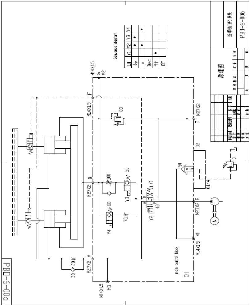
Hydraulic synchronized press brake system with torsion bar
Principle analysis
Pressure control
Start the oil pump motor.
Depending on the required bending force, use the remote control valve (10) or the proportional pressure valve to control the two-way cartridge valve (90) and adjust the hydraulic system pressure to meet the bending force requirements.
Come down
Turn on Y2 and Y3 and turn off Y1.
As the weight of the ram drops rapidly, the fill valve sucks oil into the upper cavity of the oil cylinder.
In addition, electromagnetic directional valve (PA) No. 40 and check valve No. 30 pass oil to the upper cavity of the oil cylinder.
The oil in the lower cavity of the oil cylinder passes through the 100-way one-way butterfly valve to the 50-way poppet valve, and then returns to the oil tank through the 40-way electromagnetic (BT) directional valve.
Adjust the No. 100 one-way throttle valve to control the rapid descent speed of the slider.
Work progress
Turn on Y2 and Y4 and turn off Y1 and Y3.
The normally closed fill valve (hydraulic check valve) controls pressure relief from the oil port and is closed.
Pressurized oil discharged from the oil pump passes through solenoid valve No. 40 (P → A) and check valve No. 30 to reach the upper cavity of the cylinder.
The oil in the lower cavity of the oil cylinder is returned to the tank through the No. 60 poppet valve, No. 70 butterfly valve and No. 40 solenoid valve (BT).
Adjust the co-feed speed using butterfly valve #70 and use port M2 to measure the lower cavity pressure.
l load removal
After the press brake is pressurized, Y1, Y2, Y3 and Y4 are all de-energized, and the pressure oil in the upper cavity of the cylinder passes through the 20th hole to the 40th electromagnetic directional valve (A → T) to release the pressure. Load removal time is controlled by the time relay.
Turn back
Y1 is powered while Y2 and Y3 lose power. Pressurized oil discharged from the oil pump passes through No. 40 solenoid valve (PB), No. 50 poppet valve and No. 100 one-way butterfly valve to the lower cylinder cavity.
At the same time, oil under pressure opens the filling valve (hydraulic check valve).
A large amount of oil in the upper cavity of the oil cylinder returns to the oil tank through the filling valve.
Troubleshooting common problems
Crash below
- First check whether the pressure of the safety valve in the lower cavity of No. 80 is reduced.
- Clean seat valve No. 60, seat valve No. 50 and bottom cavity safety valve No. 80.
- Stop the ramat at top dead center and completely close the 70th butterfly valve and the 100th one-way butterfly valve to assess whether the 50th and 60th east valve are damaged.
There is no slowing down or slowing down
- Check whether the plug of the 50th seat valve is loose and whether the electrical signal of the 40th directional valve is normal, and whether there is a stuck valve, such as a stuck valve that needs to be cleaned.
- Check that the 100-way one-way butterfly valve is completely released.
- Loosen the lower cavity safety valve No. 80 to determine whether the oil cylinder and guide rail are too tight.
- Check whether the fill valve is stuck.
Work not progressing at speed change point
- Check that the travel switch is set in place.
- Check that seat valves 50 and 60 are stuck.
- Check whether the fill valve is stuck. Touch the filling oil return pipe with your hand and check whether there is any oil overflow during the co-feeding phase.
- Check for a lot of air when the fuel tank returns.
- Are the system pressure and the pressure in the lower chamber M2 normal?
Unable to return or slow
- Check whether the hydraulic system is under pressure or has reached the required pressure
- Check whether the electrical signal of directional valve No. 40 is normal and whether the valve is stuck.
- Check whether port F of the fill valve control port is blocked. Whether the fill valve is stuck.
- The problem of slow return trips when valve 50 is stuck
Attached table and diagram
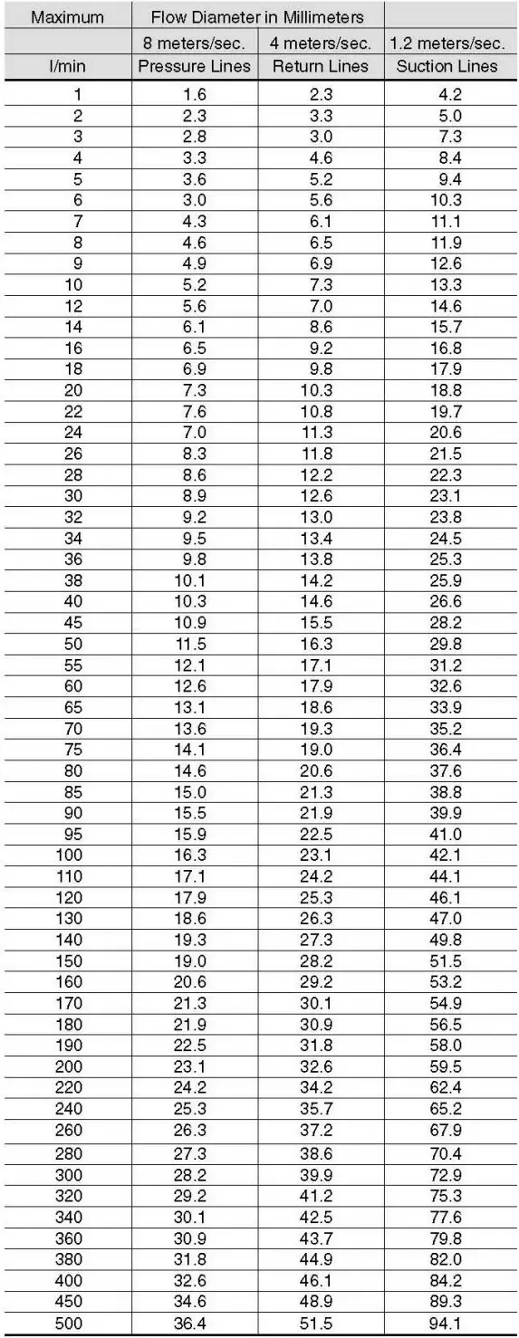
Attached table 1: Hydraulic tube diameter selection
Flow diameter
Pipe Size Determination for Hydraulic Systems
Selection of the appropriate pipe material, type and size for a given application and connection type is critical to ensuring efficient and trouble-free operation of the fluid system.
Choosing the correct pipe material and determining the ideal pipe size (OD and wall thickness) are essential when selecting the appropriate piping.
Proper pipe sizing for various parts of a hydraulic system results in an ideal combination of efficient and economical performance.
A tube that is too small causes high fluid velocity, which can have many harmful effects. In pressure lines, it causes high friction losses and turbulence, both resulting in high pressure drops and heat generation.
High heat accelerates wear on moving parts and leads to rapid aging of seals and hoses, ultimately resulting in reduced component life.
Excessive heat generation also means wasted energy and reduced efficiency.
Selecting an oversized pipe increases the cost of the system. Therefore, optimal pipe sizing is critical. The following is a simple procedure for sizing pipes:
Determine the required flow diameter
Use a table to determine the recommended flow diameter for the required flow rate and line type.
The table is based on the following recommended flow speeds:
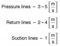
If you wish to use speeds other than those above, use one of the following formulas to determine the required flow diameter.
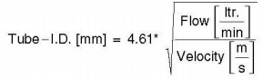
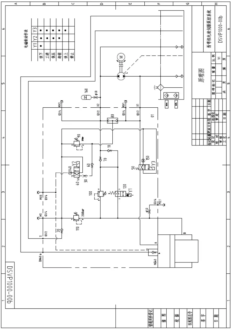
Appendix: Schematic diagram of the electro-hydraulic brake servo press hydraulic system
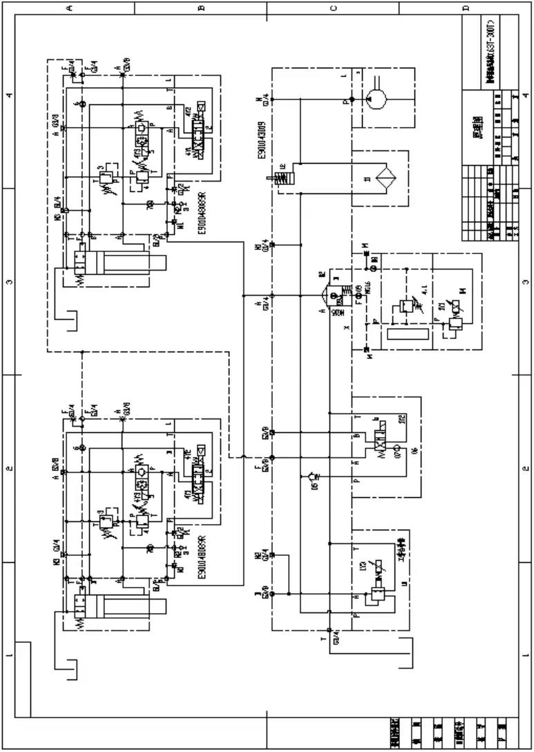
Appendix: Schematic diagram of electro-hydraulic brake servo press hydraulic system (400-1200 tons)
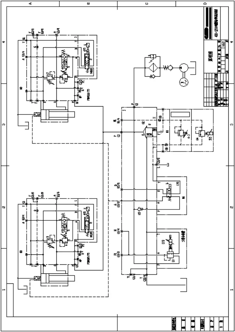
Appendix: Schematic diagram of electro-hydraulic brake servo press hydraulic system (400-1200 tons)
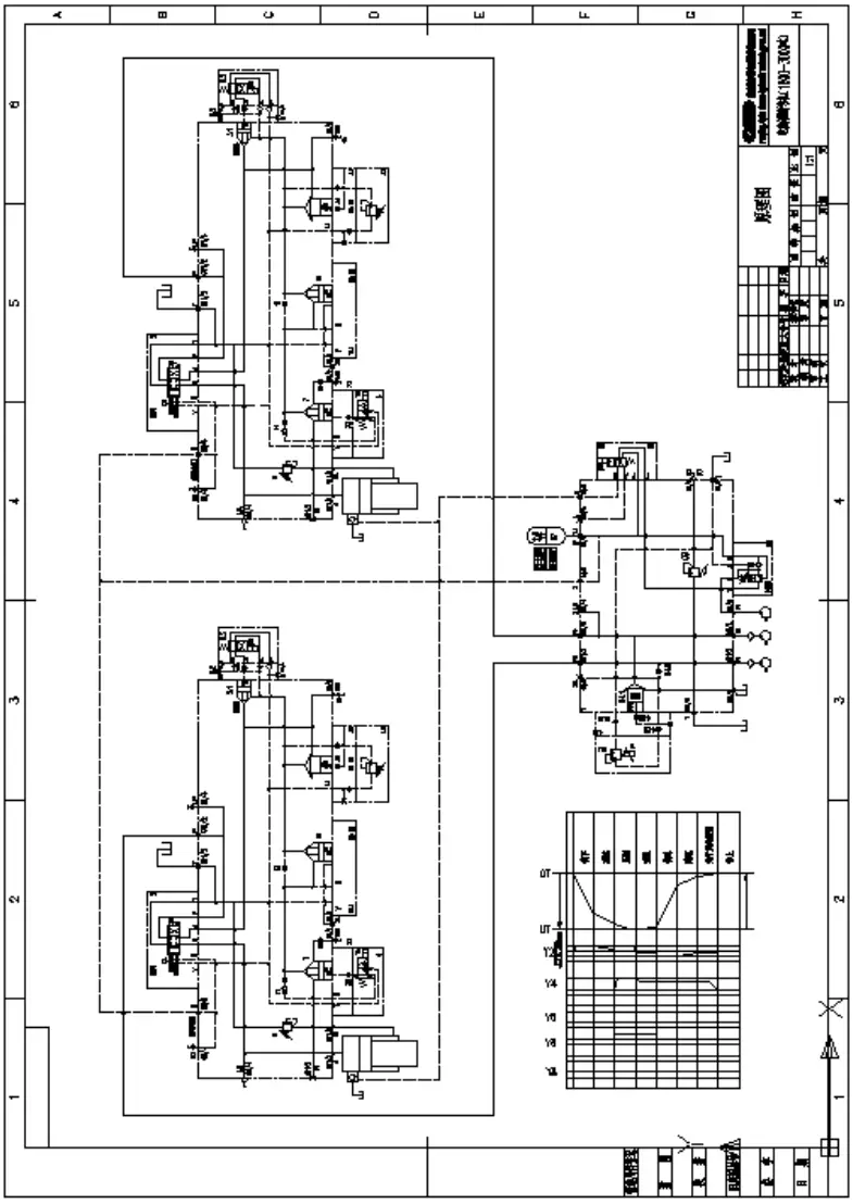
Appendix: Schematic diagram of electro-hydraulic brake servo press hydraulic system (1600-3000 tons)
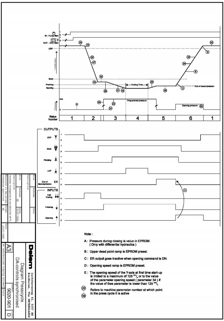
Appendix: Electro-hydraulic servo press brake timing chart
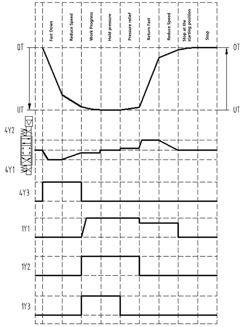
Appendix: Schematic diagram of the press brake action sequence
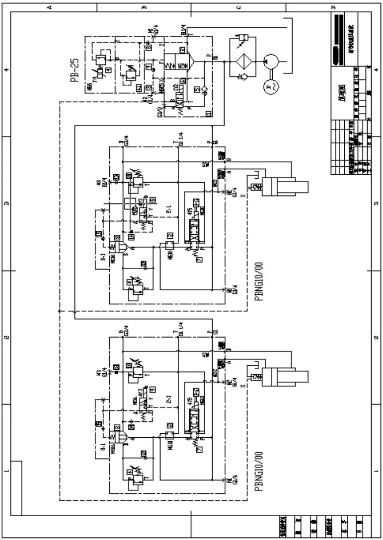
Appendix: Principle of pump-controlled hydraulic system of electro-hydraulic servo press brake
Appendix: Schematic diagram of hydraulic system for synchronized press brake with torsion bar