Quality is important in manufacturing, prices must be kept under control. There is a tendency to develop programs to reduce waste and use available resources efficiently.
Never before have precision and basic dimensions in component design and manufacturing methods been as important as they are today. It is critical that the design intent and performance characteristics of part features are clearly communicated between designers, mechanical engineers, and manufacturing facilities. This can be achieved through geometric dimensioning and tolerances.
The GD&T approach is currently used in many industries, including automation technology, mechanical engineering, aviation and others. In this article, we will have an overview of GD&T in the manufacturing industry.
Go now!
What is Geometric Dimensioning and Tolerance (GD&T)?
Geometric Dimensioning and Tolerancing (GD&T) or geometric tolerancing is a set of systems that describe the nominal geometry of a part as well as the geometric tolerance for allowable deviations. With the right tools, a designer can clearly characterize the positioning of a feature on the part and determine its geometric properties, as well as its size, shape and orientation. GD&T is designed to be used in conjunction with the Basic Dimensions and Coordinate Dimensioning System and not as a replacement for it.
The terms “geometric product specifications” and “geometric sizing and tolerance” refer to the shape, size and positional relationship of a product, while “tolerance” refers to the allowable error.
Designers and engineers use this international language to accurately describe feature size dimensions, shape, orientation, and position in their drawings. The GD&T technique takes into account the function of a component and the way in which that part interacts with other parts. To use GD&T effectively, an in-depth understanding of component function within an assembly is required.
Importance of GD&T in manufacturing and production
GD&T is an important tool that helps engineers communicate a design's tolerances. It is a precise language that allows for a consistent interpretation of a drawing. GD&T also allows the manufacturing and testing of a product. When used correctly, it can help reduce waste, rework and production delays. Below are some of the important aspects of GD&T.
Ensuring the necessary tolerance
A robust GD&T process ensures accurate compliance with all basic dimensions and geometric tolerance parameters, clearly expressing all design requirements early in the process.
Provide assistance with digital design methods
Clear and simple GD&T data can be easily converted into digital design systems, including 2D and 3D CAD software commonly used in practice.
Provides uniformity and comfort
Because Geometric Design and Technology (GD&T) is a unified language across technical drawings, guesswork and interpretation are eliminated while geometries remain consistent throughout the design and production processes. In theory, all dimensions should not be subject to more than one interpretation.
reduce costs
To improve design accuracy, GD&T allows for acceptable tolerances that promote manufacturing efficiency. In many projects, the process provides additional tolerances or bonuses that further improve the cost-effectiveness of the material condition.
Make communication easier
Today's complicated projects demand the most accurate and reliable communication. GD&T helps designers, manufacturers and inspectors communicate effectively with each other, resulting in time savings and increased efficiency at maximum material conditions throughout the process.
How does GD&T work?
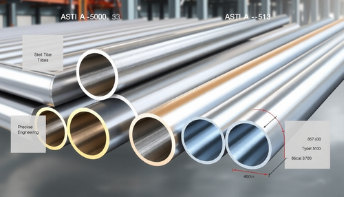
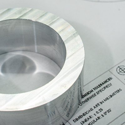
GD&T information is usually noted on technical drawings. These drawings must include dimensions for all aspects of a part. Along with the defined dimensions, a tolerance value with a minimum and maximum allowable limit must be specified. The tolerance zone is defined as the difference between the minimum and maximum values. For example, if we accept a table with a height of 750mm to 780mm, the specified tolerance is 30mm.
However, the table tolerance indicates that we would accept a table that is 750mm high on one side and 780mm high on the other side, or that has a corrugated surface with 30mm wobble. Therefore, to properly tolerate the product, we need a symbol that conveys the design intent of a flat surface. Therefore, in addition to the general height tolerance, we need to specify a flatness tolerance.
Likewise, a cylinder with a tolerated diameter is bent slightly during the manufacturing process, so that it does not always fit in its bore. In this case, straightness control is required, which is difficult to achieve with traditional plus-minus tolerances. Or if a pipe is welded to a complicated surface, surface profile control will be required.
GD&T is developing a library of symbols to communicate these geometric properties and design objectives, which we will describe in more detail in the next section.
Tolerance is the art of specifying exactly the correct variations for each individual design element to optimize product acceptance rates within manufacturing processes and in accordance with the aesthetic and functional purpose of the component.
International Tolerance Classes (IT) exist in the metric system and can also be used to indicate tolerances through symbols. For example, the designation 40H11 indicates a 40 mm diameter hole with a loose fit. The manufacturer then only needs to consult the basic hole function table to obtain the exact tolerance value.
In addition to individual tolerances, engineers also need to consider system-level consequences. For example, if a component is manufactured to the highest possible dimensions, does it still meet general criteria such as product weight and wall thickness? This is called Maximum Material Condition (MMC), while Minimum Material Condition (LMC) is the opposite.
The basic idea behind GD&T is that each part has a basic size and shape. Tolerances define how much deviation is allowed. GD&T also defines how parts should align with each other. This ensures they fit properly and function as intended.
Different Types of GD&T Symbols
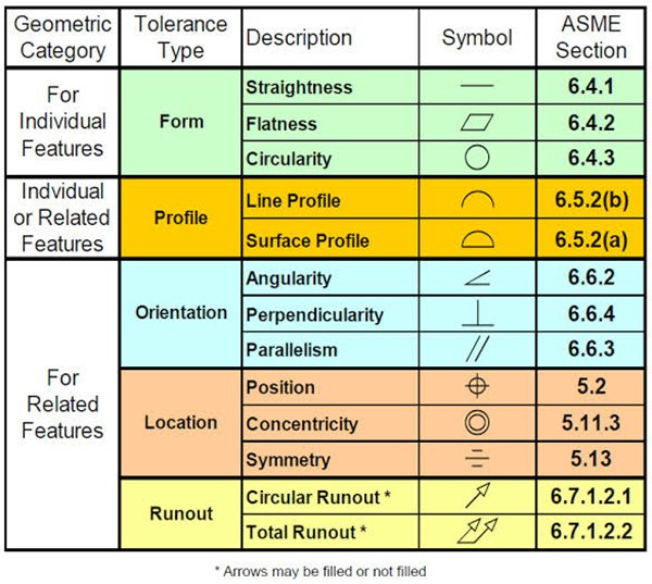
GD&T is a feature-based system for defining the size, shape, and location of features on parts. Geometric tolerances are applied to features through feature control structures. The most commonly used tolerance categories are shape, profile, orientation, position and concentricity.
GD&T symbols are clearly grouped into several groups according to their intended function.
Control of shape tolerances
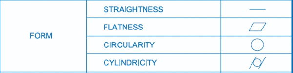
Shape controls define the overall shape of a feature, including straightness, flatness, roundness, and cylindricity.
righteousness
Also called straightness level, it refers to the actual linear geometry of a component that maintains an ideal straight line. Straightness tolerance refers to the maximum deviation of the actual line from the ideal straight line.
planicity
Flatness, also known as degree of flatness, is the actual flat shape of a component that maintains an ideal level. The flatness tolerance is the greatest deviation of the actual surface from the ideal plane.
Circularity
Circularity is often referred to as the degree of roundness. It is the actual circular shape of a component that maintains a constant distance from its center. The largest allowable deviation between the actual and ideal circle in the same cross section is called the circularity tolerance.
Cylindricity
Cylindricity means that every point on the component's cylindrical surface is the same distance from its central axis. The cylindricity tolerance is the largest allowable deviation between the actual cylinder and the ideal cylinder.
Profile tolerance control
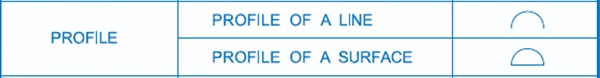
Profile control describes the three-dimensional tolerance zone around a surface. Includes the profile of a line and the profile of a surface.
One-line profile
The line profile of a part in the state of a curve of any shape in a specified plane that maintains its ideal shape. Line profile tolerance refers to the deviation that can occur in the actual contour of an irregular circular curve.
Profile of a surface
The profile of a surface is the condition that indicates the surface of any shape of the part, maintaining its ideal shape. It is the actual contour line of the non-circular surface and the degree of variation allowed for the ideal contour surface.
Orientation Tolerance Control
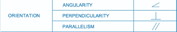
Orientation control defines the position of features and handles dimensions that vary at different angles, including angularity, perpendicularity, and parallelism.
Angularity
The Skew property specifies that the relative orientation of two elements in a part is maintained within the specified angular dimension. Slope indicates the tolerance for the maximum allowable deviation between the actual orientation of the tested element and the ideal orientation at any specified angle relative to the reference point.
perpendicularity
The perpendicularity or degree of orthogonality between two elements indicates that the measuring element in a component maintains a correct angle of 90° with respect to the reference element. The perpendicularity tolerance is the difference between the actual direction of the measuring element and the maximum allowable deviation between the orthogonal directions predicted for the reference phase.
parallelism
Parallelism, often referred to as the degree of parallelism, is the distance at which the actual elements of a part remain the same as the reference plane. The maximum allowable deviation between the actual direction of the measured element and the expected direction of planes parallel to the reference plane is the parallelism tolerance.
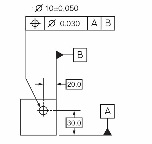
Position tolerance control
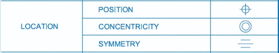
Location controls determine the location of a feature using linear dimensions, including position, concentricity, and symmetry.
position
The degree of localization refers to the precision with which a point, line, surface, or other feature is located on a part relative to its predicted location. Position tolerances refer to the greatest deviation from the actual position of the measured element compared to the ideal position.
Concentricity
Sometimes abbreviated as coaxial degree, it refers to the fact that a component's measurement axes are parallel to a reference axis. Coaxial tolerance refers to the allowable deviation of the actual measurement axis from the reference point.
symmetry
Symmetry refers to the state of a component in which two symmetric central components lie on the same central plane (or centerline, axis). The allowable deviation of the ideal plane of symmetry from the central plane of actual symmetry is called the symmetry tolerance.
Control of concentricity tolerances
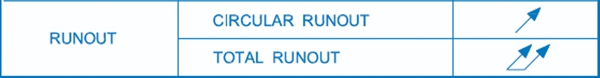
Concentricity controls define how much a given feature can deviate from reference points. This includes circular deviation and general deviation.
Circular running
The term “circulation” refers to a condition in which the rotating surface of a part lies within a specific measurement plane and maintains a constant position relative to the reference axis. Within a certain measuring range, the maximum allowable deviation is the deviation tolerance when the actual measured component is rotated completely around the reference axis without axial movement.
Full circularity
When a component continuously rotates around the reference axis, the total deviation refers to the amount of deviation as well as the entire measured surface. The total deviation tolerance is the maximum deviation allowed when the actual element under test rotates continuously around the reference axis and the indicator generally moves along its predicted contour.
Shape and position tolerances in GD&T
What is a resource control framework? In geometric design and technology, a feature control framework is used to explain the requirements and tolerances of a geometric control applied to a feature of a part. The resource control framework consists of four main pieces of information, including:
-
GD&T mark, also known as control symbol
-
Shape and size of the tolerance zone
-
Various tolerance zone modifiers are available, such as: B. Material state modifiers and projections
-
Date references
This information will give you everything you need to know about understanding geometric tolerance, measuring, and deciding whether the part is within specifications.
Parts of the tolerance chart
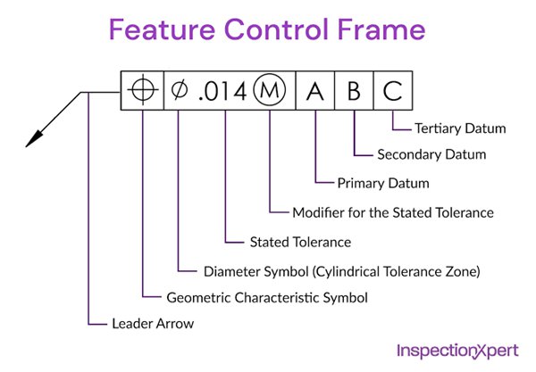
The parts of a tolerance chart include the guide arrow, geometric symbols, tolerance zone, etc.
- Leading arrow
This arrow draws attention to the element where the geometric control is located. (As stated, the extension line may or may not be used.)
- geometric symbol
Specify the geometric control you want to use here.
- Diameter symbol
If the geometric control is a diameter tolerance, this symbol (Ø) appears before the tolerance value.
- Specified value or tolerance value
The tolerance zone indicates the overall tolerance of the geometric control. The unit of measurement and basic dimensions are determined by the drafting standard.
- Size or tolerance modifiers
Here you can identify all features where special tolerances need to be taken into account. For example, a feature with tight tolerances may require a larger datum target than a feature with looser tolerances.
- Date Resource Reference (Primary Date Resource Reference)
This is the main reference resource used for GD&T control when a reference is needed for control. The letter refers to a feature of the part that will be marked with the same letter when the part is completed. When measuring the component, this is the reference feature that must first be limited to be accurate. It is important to note that the order of the reference feature is crucial for measuring the component.
- Secondary frame of reference
Secondary reference points are specified to the right of the primary reference point, if necessary. This letter refers to a feature of the part that is marked with the same letter in the same location on the part. This is the reference set after the main reference during the measurement process.
- Tertiary date characteristics reference
If necessary, the third waypoint will be linked to the right of the secondary waypoint feature reference. This letter refers to a feature of the part that is marked with the same letter in the same location on the part. During the measurement process, this is the last set reference point.
Application of GD&T in practice
GD&T has the advantage of describing design intent rather than actual geometry. Similar to a formula or vector, it is just a representation of the element.
To reduce assembly errors and the effort required for quality control, statistical process control (SPC) can be used with GD&T. This is a huge cost saving for businesses. Thanks to GD&T, many departments can collaborate on the same project because they all speak the same language and have the same goal in mind. GD&T is therefore used in diverse situations in production and manufacturing.
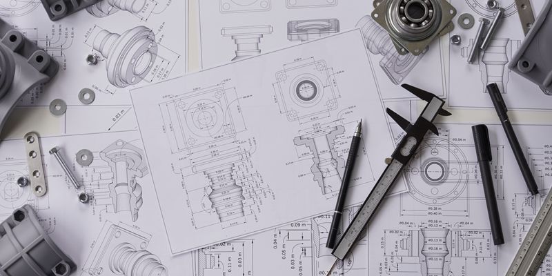
GD&T in the drawing
The technical drawing serves as checks and balances to ensure that the supplier produces exactly what the customer's project requires. +/- 0.002 is a very tight tolerance when it comes to accuracy. “The use of GD&T will become even more important. Cylinders that need to be “cylindrical” need to be cylindrical to the nearest 0.0003.” “In this case, for example, you can start very quickly.
GD&T in CNC machining
One of the advantages of CNC machining is the ability to produce parts to very tight tolerances. This is possible because the cutting tools are controlled by a computer, which allows very precise movements. To make the most of this opportunity, it is important to use correct form and position tolerances.
In CNC machining, GD&T is used to set tolerances for each dimension of the part. This ensures that the finished part meets the design requirements. GD&T is also used to specify the location of features on the part, for example. B. Holes and grooves. This ensures that features are machined in the right place and aligned correctly.
Although not all CNC machined parts require technical GD&T skills, GD&T is a good method when advanced CNC machining is required. Consider the following 5 benefits of using GD&T in CNC machining:
- Easy communication
GD&T allows you to communicate a variety of information about your part design using a limited number of characters, numbers and symbols. Long explanations are no longer necessary! The ability to communicate effectively reduces the time spent between you and your contract manufacturing service provider.
- Precise production
Because of the precision with which GD&T is formulated, ambiguity when describing the design of a CNC part is minimized. Therefore, you can be assured that your product will be manufactured with precision and will perform as intended during use.
- Known tolerances
GD&T provides manufacturers with a comprehensive view of the tolerances associated with a specific item. It provides the highest tolerance necessary for the CNC component to function properly, simplifying the part and avoiding waste with a minimum tolerance that you may not need.
- Universal language
You may need to work with a contract manufacturing company in a country whose native language is not English. Good news! GD&T is a globally recognized universal language that eliminates cumbersome language barriers for international manufacturing.
- Correct assembly
If you have two mating CNC components that need to be connected in an assembly, GD&T is a good way to communicate how to make that connection. In these cases, GD&T clearly displays the tolerances for each element, allowing manufacturers to quickly determine if a measurement is incorrect and modify it accordingly.
GD&T in 3D printing
The use of GD&T in 3D printing is becoming increasingly popular as the technology advances. This is because it provides a more accurate representation of the finished product, which can be extremely useful when producing complex parts.
For GD&T to be effective, it must be used in conjunction with accurate measurements. 3D printing is an additive process, meaning the final product is built layer by layer. Therefore, it is important to take into account the fact that each layer is slightly different from the one below it. This can lead to inaccuracies in the final product if GD&T is not used correctly.
Many product designers and engineers use 3D printing for rapid prototyping and rapid tooling throughout the product development process to create cost-effective prototypes and unique components that would otherwise require significant tooling.
Tolerances in 3D printing differ from tolerances in traditional manufacturing equipment because 3D printing is a single, automated process. While tighter tolerances require more work in the design phase, they can result in significant time and cost savings during prototyping and production.
Concluding
GD&T is an efficient method for describing the dimensions and tolerances of a project. It communicates the design purpose and functional requirements of a component in a clear and understandable way. If you want to ensure that the parts you design are perfect for the function they are intended to fulfill, then GD&T is for you.
We have extensive machining capabilities that allow us to serve customers from all industries with high tolerance requirements. Furthermore, we offer 100% inspection of parts before sending them to you. Get an instant quote today!
Common questions
What is GD&T used for?
GD&T is used in the engineering and manufacturing industries to describe the precise tolerances or deviations from nominal geometry allowed for a part or assembly.
What GD&T standards are used in different countries?
GD&T is a global engineering language that may vary slightly from country to country, but most of the content is the same.
American Standard: ASME Y14.5-2009
International Standard: ISO 1101-2012
Chinese standard: GB/T 1182-2008 (equivalent to ISO1101)
German standard: DIN ISO 1101 (equivalent to ISO1101)
Japanese standard: JIS B0021 (equivalent to ISO1101)
British Standard: BS ISO 1101 (equivalent to ISO1101)