1. Objective
To guide bending personnel in more rational selection of molds, improve the service life of molds and reduce abnormal wear.
2. Function
To reduce the time required to select bending molds, increase production efficiency and reduce costs.
3. Scope of Application
Sheet metal bending operations.
4. Basics of press brake tools
General purpose
General purpose tools are manufactured from pre-hardened tool steel with a Rockwell hardness range of Rc 28-30.
Tooling generally runs the entire length of the press brake base, with nominal size and straightness tolerances depending on the tool manufacturer.
Sectioned general purpose tools must be marked to match since individual sections may not be interchangeable due to variation in manufacturing dimensional tolerances.
Hardened general purpose flame
Several press brake tool manufacturers offer flame-hardened tooling for better wear resistance at the die shoulders and punch tip radius.
This tooling may be less accurate in straightness, due to the heat treatment process and subsequent mechanical straightening.
General Purpose Four-Way Arrays
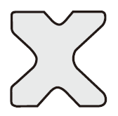
The four-way die has four different “V” female openings, each of which is accessed by rotating the die.
The disadvantage of this configuration is that the minimum flange of a part to be formed cannot be smaller than the width of the four-way die.
Although changing the female opening is simple, the die and die holder must be centered with the punch for each rotation to ensure optimal press brake forming performance.
Adjustable Arrays
Adjustable dies provide a variety of openings – in 1/2” increments from a minimum of 1” to a maximum of 8”, 10” or 12”. An opening is set by moving the key-adjustable tie rods to a key position of the interlocking base plate.
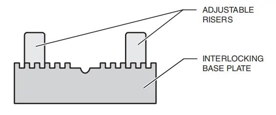
This type of die is useful for forming a wider range of material thicknesses. It is especially favorable because the wider openings allow for thicker plates to be formed.
Punches
A variety of punches are available for different forming techniques. See the tools' documentation for information about specific applications.
Precision ground and hardened dies
Precision ground and hardened tools are manufactured in sections to tighten dimensional tolerances and allow for direct exchange and replacement.
Precision tools are geometrically defined with specified die height, die opening and shoulder radius, punch radius, and load rating – all of which can be cataloged in a press brake CNC measuring system tool library.
Defining tool geometric parameters in a CNC environment increases press brake productivity because it reduces the number of trial bends and sample parts required to set up the job.
Holders for press brake dies
1. Standard Matrix Support:
The standard die holder serves as a filling block between the press brake base and the press ram to ensure die closure within the full stroke of the press brake. In most cases, tooling alone will not fill the closing height.
The die holder also serves as a work surface to minimize wear on the press brake base during die changing.
The die holder allows the die set to be lifted onto shims located to accommodate angle variations of the formed part. These variations are due to irregularities in general-purpose dies and wear, usually associated with continuous braking of the press in the same area.
Die holders can be prevented from moving or mechanically adjusted at the base of the press brake by a tenon and set screws, T-screw fasteners, or die adjusting blocks.
2. Four-way matrix support:
The four-way die holder is a channel that retains and centers a four-way die with the punch during forming.
The four-way die holder is similar to the standard die holder in terms of function and attachment to the press brake.
3. Crowned Die Bracket:
Several tool manufacturers offer die holders crowned with:
- single adjustment for proportional crowning of the matrix holder over the entire length, or
- individual adjustment points along the length of the die holder.
An advantage of the crowned die holder is that the operator can make adjustments to the die set without traditional die holder shim procedures.
The clamping height and dimensional stack for the clamping height of the press brake are similar to those of the standard die holder.
5. Selection of press brake tools
4.1 The commonly used upper punch includes: 88° straight punch (R1), 30° sharp punch/acute straight punch (R1/R0.5), 88° gooseneck punch (R1), straight gooseneck punch of 88° (R1/R0.5). ), flattening punch and specialized molds for superior dies.
4.2 Commonly used bottom die for bending includes: single/double V bottom dies with angles of 30° and 88°, V4, V6, V7, V8, V10, V12, V16 and V25 (mm).
4.3 Bending die selection is generally based on the bending blade sequence arrangement after reviewing the drawings.
4.4 Selecting the upper matrix according to the angle:
4.4.1 When the processing angle is greater than or equal to 88°, use a superior die with an angle less than 88° (e.g. straight blade, sharp blade/sharp straight blade, curved blade, curved straight blade, etc.) .
4.4.2 When the processing angle is less than 88°, use a higher 30° die (e.g. sharp blade/sharp straight blade).
4.4.3 When it is necessary to press a dead edge, use a sharp blade/sharp straight blade to form an acute angle (generally 30°), and then use a flattening die to flatten the pressed edge.
4.4.4 When the plate thickness exceeds 3 mm, avoid using sharp blades/sharp straight blades to avoid damage to the tool.
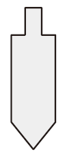
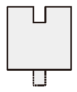
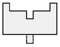
4.5 When it is necessary to process a U-shape based on external shape requirements.
When ba ≥ 5 mm, you can choose between sharp punch (sharp straight blade), straight punch (straight blade), straight gooseneck punch (curved straight blade) or gooseneck punch (curved blade).
When 1 mm < ba < 5 mm, you can choose between straight gooseneck punch (straight curved blade) or gooseneck punch (curved blade). When ba < 1 mm, you can choose gooseneck punch (curved blade).
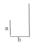
Note: A and b > 6 mm and 100 mm > a, b are internal dimensions. When you need to process a Z shape, you usually choose between straight punch (straight blade), sharp punch (sharp blade/sharp straight blade), straight gooseneck punch (straight curved blade) and gooseneck punch (curved blade).
4.6 Lower matrix selection:
4.6.1 The size of the V-groove is generally chosen based on six times the thickness of the plate.
4.6.2 Select the lower matrix according to the angle: when the angle is greater than or equal to 88°, you can choose between lower matrices of 88° or 30°; when the angle is less than 88°, choose a 30° lower die (measure the effective height of the upper die: the distance from the upper die to the edge of the blade on the force-receiving surface of the upper die clamp).
4.7 When splicing upper and lower dies, the following points must be considered:
4.7.1 Do not mix molds with different heights during selection, as this may cause inappropriate angles, damage the molds or even cause work accidents.
4.7.2 When selecting a top mold for a hemmed door panel, consider the quality of product processing and ease of handling, generally leaving a gap of 3-6 mm at both ends (if necessary, consider using an “edge blade”).
4.7.3 Avoid using damaged molds for product processing to avoid poor appearance, and inspect the straightness and flatness of the upper mold cutting edge after installation.
4.7.4 When avoiding positions, be aware of appearance quality issues such as avoidance point setback and insufficient angles.
4.8 Mold selection under abnormal conditions:
4.8.1 For pressing lines, choose a sharp, pressure-resistant blade for the upper mold and a flat, aligned lower mold with no steps between the upper and lower molds.
4.8.2 When processing U shapes, if the inner dimension of the opening is less than 6mm, first use a curved blade to bend the opening larger than the second blade size, and then press it to ensure the dimension or use a specialized mold to shape.
4.8.3 When processing products with specific requirements for inner R radius, consider in advance a top die mold with corresponding R radius when selecting the top die mold (e.g. inner R radius requirements of R0.3, R1, R4 , R8, or R10).
4.8.4 When bending 6mm with 2.0mm plate thickness, choose 88° V8 bottom die; When bending 10mm with a plate thickness of 3.0mm, choose an 88° V12 bottom die to prevent the workpieces from slipping and becoming impossible to process due to excessively small processing dimensions.
4.8.5 When processing round steel, use specialized molds and have a dedicated operator.
4.9 When selecting upper punch/lower die molds, try to avoid splicing to avoid seam marks and maintain a good appearance of the product.
4.10 When calibrating upper/lower die molds, use molds greater than or equal to 300 mm for calibration. Do not use small spliced molds or molds smaller than 300 mm for calibration. For molds longer than 1 m, the difference in length between the upper and lower molds should not exceed 20%.
4.11 Before installing the mold, be sure to check whether the limited stroke of the machine is greater than the total height of the upper/lower molds to avoid damage to the mold and work accidents.
4.12 Check whether the mold is locked before calibration and recheck the tightness of the mold after calibration.
4.13 Do not place unused molds in the equipment to prevent the molds from falling, causing damage or injury.
4.14 After using the mold, immediately return it to the designated mold holder and place it in an organized manner.
4.15 Do not install two molds of different heights on the equipment at the same time.
4.16 The workshop must regularly maintain and repair molds and clearly mark them.