I. Selection of copper busbar
1. Rectangular copper busbars should be used as much as possible for primary wiring.
When it is difficult to process with rectangular busbars or the current is less than or equal to 100A, insulated wires can be used.
Copper busbars are generally used for machine room type distribution cabinets.
2. Primary bus selection:
2.1 If there are requirements in the drawings, the busbar must be selected according to the requirements in the drawings (the busbars of the main input line cabinet and the contact cabinet are selected according to the confluence).
When there are no specific requirements in the drawings, the busbar must be selected in accordance with the provisions of this process code.
2.2 The selection of branch buses should generally be based on the rated working current of the thermal trigger of the automatic pneumatic switch. Other selections must be made according to Table 1.
Table 1 Requirements for bus selection
| Form | Conditions for choosing a bus |
| Automatic air switch without thermal release. | According to the rated current value of the pneumatic switch. |
| There are several branch circuits below the automatic pneumatic switch, each equipped with its own automatic pneumatic switches. | According to the current value of the branch circuit. |
| The circuit consists of a knife switch, a fuse and a current transformer. | Based on the rated current value of the primary side of the current transformer. |
| Contactor only | Based on the nominal current value of the contactor. |
| Fuse only | According to the rated current value of the fuse. |
Explanation: When adjusting the thermal trip of a molded case circuit breaker, select according to the maximum value.
3. Current carrying capacity of the bus
3.1 The busbar of the 8PT cabinet is selected according to the cross section specified in the technical table of busbar materials. For parts not specified by material, use Table 2 for selection:
Table 2 Selection of current carrying capacity for non-standard buses in 8PT cabinet.
| Rated current (A) | copper bus | |
| Rigid bus | Soft bus | |
| 160 | 2*20*1 | |
| 175~225 | 20*5 | |
| 225~250 | 25*5 | 4*20*1 |
| 250-275 | 30*5 | |
| 275~350 | 40*520*10 | |
| 350-400 | 30*10 | 5*32*1 |
| 400~500 | 30*10 | |
| 500~630 | 40*10 | 8*40*1 |
3.2 For standard products, please refer to the company's bus selection table:
3.3 The cross-section of the protective conductor must be chosen according to Table 4. If the wire selected according to Table 2 is not of standard size, it must be adjusted to the standard specifications of the bus.
Table 3
| Cross-sectional area S (mm 2 ) of the device phase line | The minimum cross-section of the corresponding PE protective conductor Sp (PE, PEN) mm 2 . |
| ≤16 | s |
| 16<S≤35 | 16 |
| 35<S≤400 | S/2 |
Note 1: When the protective conductor is used as PEN, it is permitted as long as the neutral conductor current does not exceed 30% of the phase current. When it exceeds 30% of the phase current, the cross section of the corresponding protective conductor needs to be increased. The PEN protective conductor bar does not require insulation.
Note 2: When non-standard cross-sectional dimensions are obtained from this table, the next larger size should be selected.
3.4 The color of the bus and device wires must be in accordance with the provisions of GB2681-81 “Wire Colors in Electrical Equipment Assemblies”, and their phase sequence is shown in Table 4 (viewed from the front of the cabinet).
Table 4: Bus arrangement sequence
| Category | Signals | Vertical arrangement | Horizontal arrangement | Arranged from front to back | |
| Alternating current | Phase A L1 | Yellow | Main | Left center Right Far right Far right |
Distant |
| Phase B L2 | Green | Quite | Left | Average | |
| Phase C L3 | Red | Bottom | center | Zoom in | |
| Neutral Line N | Light blue | Lower | Right | Closer | |
| PEN Protective Earth Neutral Line | Yellow-Green Alternation | Lower | Far right | Closer | |
| PE Protective Line | Yellow-Green Alternation | – | – | – | |
| Direct current | L+ Positive Terminal | Brown | Main | Left | Distant |
| Negative terminal L- | Blue | Bottom | Right | Zoom in | |
| Neutral to Earth M | Light blue | – | – | – | |
Explanation: The bus arrangement order of the 8PT product refers to the default order generated by the 8PT software.
3.5 Identification of the Bus Phase Sequence:
The identification of the main bus phase sequence can be marked with colored and printed labels. Color labels are the preferred method. When using printed labels, the printing must be clear, well pasted and firmly attached.
When using color labels, the color of the labels must comply with the specifications in Table 5.
The PE bus is marked with a double yellow-green color and a PE symbol. Dimensions of color labels are specified in Table 5.
Table 5 Diameter of color labels
| Bus width | Color mark diameter |
| 15mm | φ15 |
| 20, 25, 30, 40, 50mm | φ20 |
| 60, 80, 100, 120 | φ30 |
Explanation: 8PT buses are packaged and labeled with two-color identification strips L1, L2, L3, N and yellow-green.
3.6 The minimum distance between the horizontal and vertical arrangement of the busbar and the bottom of the structure must not be less than 200mm, including rows N and PE.
3.7 When N and PE lines use M8 or larger screws for input and output wires, the holes are configured with external hex screws; When using M6 screws, the holes are configured with internal hex screws.
3.8 The arrangement of the busbars must guarantee the operating space for directly operated electrical equipment (that is, the busbars must not compromise operator safety during normal operation).
II. Bus processing steps
1. Select lines according to the drawing (those not specified in the drawing are selected according to this process) and determine the size of the wiring diagram.
The shape and size of the bus are generally determined by the processor, and standard products and drawings with special requirements are made according to the drawings.
2. Cut the material, adjust the busbar to be straight and level.
3. Mark lines, drill or drill holes, deburr and chamfer the end faces.
4. Flexion (flat flexion, vertical flexion, twisted flexion).
5. Surface tin treatment.
Note: For some special busbar sizes that are difficult to measure and process, an additional length of 150 mm can be reserved, bending can be performed, and then holes can be drilled.
6. Busbar manufacturing requirements
6.1 Busbar production should consider safety and reliability after installation, convenience for inspection and disassembly.
6.2 The busbar itself must be very straight and any crooked or irregular busbar material must be corrected. Generally, a straightener is used for correction or corrected manually with a wooden hammer.
However, buses fixed in this way should not show obvious hammer marks. After correction, the bending degree of the wide surface of the busbar shall not exceed 2mm per meter, and the lateral shall not exceed 3mm per meter.
6.3 The processed parts of the busbar must have no burrs, and the end face must be perpendicular to the edge of the busbar (except for special requirements). The busbar must be deburred on both sides after drilling.
6.4 When it is necessary to connect the secondary power wires to the primary copper busbars, drill a Ф6 hole in the busbar and connect it with an M5 screw. Hole Ф6 is drilled 30 mm away from the bus joint and 8 mm from the edge. Remove a 15 × 15 mm bare surface from the busbar equipped with a heat shrink wiring sleeve.
6.5 Refer to the busbar punching table “Main Circuit Primary Process Guidelines” for the busbar joint punching size, which mainly includes straight and vertical connections. When the distance between busbars exceeds the length of Table 6, an additional fixed support must be added.
Table 6
| Bus width (mm) | Support distance (mm) |
| ≤30 | 300 |
| ≤50 | 600 |
| ≥60 | 900 |
6.6 The distance from the starting point of the busbar bend to the nearest edge of the busbar support clamp shall not be less than 50mm and shall not exceed 0.25L (L is the distance between two busbar support points, generally 1m ), see Figure 1.
6.7 The distance from the starting point of the busbar bend to the busbar overlap position should not be less than 20 mm, see Figure 2.
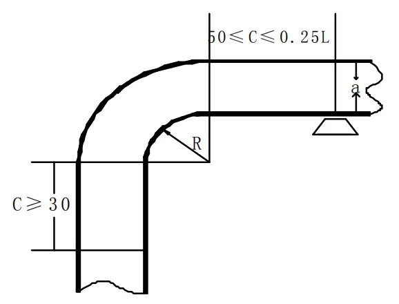
a refers to the width of the bus
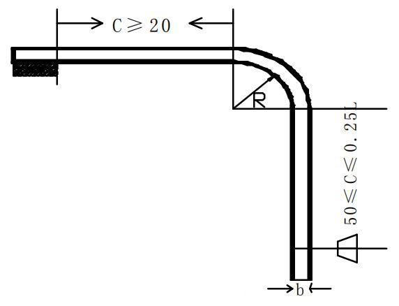
b refers to the thickness of the busbar
6.8 The busbar can be bent, vertically or twisted as required. The radii for flat and vertical bends must be made in accordance with the values listed in Figures 1 and 2 and Table 7.
Table 7: Minimum Curvature Radius (R) Values for Busbars
| Bus type | Bending Methods | Bus transverse dimensions | Minimum bending radius (mm) |
| Copper | |||
| Rectangular Bus | Flat push-up | 50×5 and below 120×10 and below |
2b 2b |
| Vertical Flexion | 50×5 and below 120×10 and below |
1 one 1.5a |
6.9 Rectangular busbar processing at 90 degrees
When twisting a busbar 90 degrees, operations can be performed in a bench vise. Place a block of copper in the jaws of the vise, clamp the leading end of the busbar to be bent vertically between the jaws, use an adjustable wrench or other specialized tools to rotate the busbar 90 degrees to an appropriate location.
The minimum busbar torsional distance is 1.5 to 2 times the width (b) of the busbar. The specifications for this process are thickness ≤6mm and bus width ≤60mm. The specific form can be seen in Figure 3.

6.10 The starting and ending points of the flat curve, vertical curve and twisted curve of the three-phase bus in the same circuit must be consistent.
6.11 When several rectangular busbars are used in parallel for a circuit, there must be a gap not less than the thickness of the busbar between the parts.
6.12 Processing details:
Processing steps:
Measure → Cut → Straighten, Level → Mark → Drill → Bend → Outsource Surface Tin Plating → Install → Stick Label
Observation:
① Process the 8PT copper bar according to the standard drawings formed in the 8PT software, and corrections need to be made to those that should be positively superimposed by the technical agreement.
② Measure the copper bar by finding a fixed point on the cabinet and don't forget the thickness of the copper bar.
—Copper Bar Diagram: Generally, three views are used, in projection method – main view, top view, left view.
—Technical requirements to be marked on the copper busbar processing diagram:
①. Unit: ** mm
②. Specification: ** × ** width * thickness
③. Tolerance: +/-0.3mm
④. Quantity: ** pieces
⑤. Installation location:
— Calculation of unfolded material:
1). Bend right angle:
①. The basic rule for bending a right angle bend is: Length of unfolded material = total length measured externally – bar thickness*1.77 (mm).
②. For a busbar bent at right angles with a thickness of less than 6 mm, use an R5 mold for bending, and for those above 6 mm, use an R10 mold for bending.
③. Specific reduction coefficient (each outer dimension of right-angle curvature is measured once and the coefficient is reduced once), see Table 8:
Table 8
| Bus material thickness (mm) | Required dimension reduction (mm) | Bus material thickness (mm) | Required dimension reduction (mm) |
| 3 | 5.3 | 6 | 10.6 |
| 4 | 7.1 | 8 | 14.2 |
| 5 | 8.9 | 10 | 17.7 |
2) Oblique Curve:
Calculated according to the Pythagorean theorem, with small deviations.
Key points to note:
—There must be no burrs on the cross-section of the copper busbar.
—There should be no burrs on the edges of the drilled holes.
—There should be no marking pen marks on the surface of the copper busbar during installation.
—When applying a heat shrink sleeve to the bus surface, use a heat gun to heat it evenly. There should be no uneven heating pits on the surface.
—When peeling off the heat shrinkable cover, use a square ruler to press the paper knife and peel it off in a straight line. The tin layer on the surface of the copper busbar must not be scratched, exposing traces of bare copper.
—Consider the electrical clearance and creepage distance between busbars and from busbar to ground during busbar processing.
7. Bus installation
7.1 The bus connection method must be carried out in accordance with the overlap table specified in the process document.
7.2 In the switchboard, the busbar is usually connected with through bolts. The bus connection must be firm and have good contact. The connecting surface should fit together naturally and the configuration should be elegant and aesthetically pleasing.
7.3 The fasteners used in busbar connections must be galvanized screws, nuts, spring pads and washers that meet national standards. The 8PT product connection meets relevant process requirements.
7.4 All overlap screws must use common flat washers (concave surface facing the busbar). The threaded part of the screw should protrude 3 to 5 threads. There must be a free distance of more than 3 mm between adjacent screw washers.
7.5 When the busbar is flat, the screws must be installed according to the following rules to facilitate observation of the tightening and maintenance status: facing the electrical maintenance and operation side, the through screws must be installed from back to front and from bottom to main. In other cases, the nut should be on the maintenance side.
7.6 After installing the busbar, if there is sagging or rising between two support points, the deviation must not exceed 4mm.
7.7 The connection between the busbars must guarantee sufficient and long-lasting contact voltage, but must not cause permanent deformation of the busbar.
7.8 A copper-aluminum composite part must be installed when copper and aluminum are connected.
Precautions:
—The copper busbar needs to be protected during the tinning process. It must undergo inspection to confirm that the surface treatment is acceptable before it can be transported or installed.
—White gloves should be worn when installing copper busbar after tinning to prevent fingerprints from remaining on the surface.
—Ordinary products are installed with grade 4.8 screws, while Siemens products and other specified products are installed with grade 8.8 screws.
—The screw penetration of the 8PT product must be in accordance with the assembly diagram of the 8PT product, and the torque must meet the requirements.
—Electrical clearance and creepage distance between busbars and from the busbar to the ground.
8. Inspection
8.1 Whether the manufacturing of the primary line meets the relevant requirements of the drawings.
8.2 Whether the primary bus and selection meet the load capacity requirements.
8.3 Whether the electrical clearance and creepage distance of the bus meet the process requirements.
8.4 Tightening of screwed connections.