After 7,305 hours of operation of a diesel engine at our company, cracks were found on the piston skirt of the third cylinder.
To determine the cause of the crack, we dissected the piston skirt and conducted a comprehensive analysis and evaluation of the chemical composition, mechanical properties, macrostructure, macromorphology, and microstructure of the fracture.
1. Technical requirements for piston skirt
Our company uses forged mold for the piston skirt, made of material 4032 in delivery state T6, which undergoes solid solution heat treatment. The chemical composition of the material complies with GB/T3190.
The production process involves forging, solid solution, artificial aging and machining. After forging, solid solution and artificial aging, the mechanical properties of the piston skirt are: HBS = 100 ~ 125 (10/1000), σb≥280MPa and δ5≥1%.
The macrostructure of the fourth section must not present segregations, cracks, pores or inclusions. The flow direction of the metal generally follows the contour of the forging without flowing or bending.
For quality control, a sample is taken at the end of the pull sample, which is then examined under a microscope at 100x or 400x magnification. The sample must not contain harmful defects such as inclusions, segregation or excessive burning.
2. Crack discovery process
Below is an analysis of the photographs provided for inspection of the piston skirt.
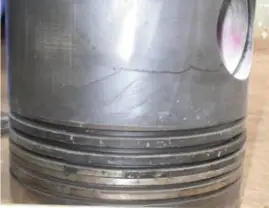
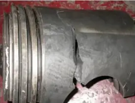
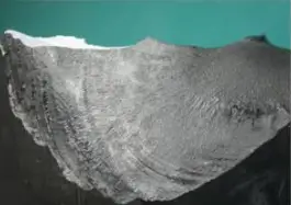
Figure 1 shows a photograph of the piston skirt with visible cracks. The cracks are transverse in nature and are located on the outer diameter of the piston. The cracks are more than 1/4 the diameter of the piston and have penetrated the wall thickness.
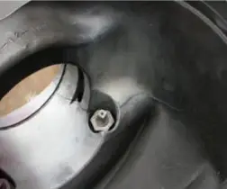
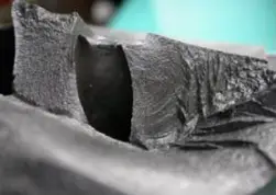
Figure 2 shows the morphology of the internal cavity crack. The crack extends from the inside of the piston through the bore to the outer surface.
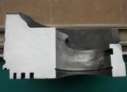
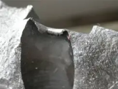
Fig. 3 shows a photograph of the piston skirt opening along the crack with an external force. The objective is to analyze the morphology of the crack fracture.
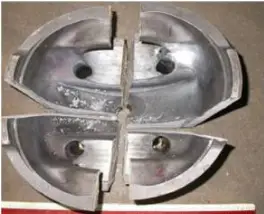
Fig. 4 is a photograph of the piston skirt dissected along mutually perpendicular center lines. The purpose of the dissection is to test and analyze the mechanical properties of the piston skirt, including the aerodynamics of the low-magnification fiber.
(1) The chemical composition of the piston skirt is inspected and the material is 4032 GB/T3190. The inspection results are shown in Table 1.
Table 1 chemical composition (mass fraction) (%)
| Element | Measured value | Application | Determination of Compliance |
| Yes | 11.82 | 11.0~13.5 | coincident |
| Faith | 0.26 | ≤1.00 | coincident |
| Ass | 0.76 | 0.50~1.30 | coincident |
| mg | 0.98 | 0.80~1.30 | coincident |
| Mn | 0.021 | – | – |
| No | 0.69 | 0.50~1.30 | coincident |
| Zn | 0.031 | ≤0.25 | coincident |
| You | 0.014 | – | – |
| Cr | 0.032 | ≤0.10 | coincident |
| Al | margin | – | – |
Conclusion: Chemical composition meets the requirements of 4032 in GB/T3190.
(2) The mechanical properties were tested and the results are shown in Table 2.
Table 2 mechanical properties test
| Project | Measured value | Application | Determination of Compliance |
| Tensile strength/MPa | 352.1 | ≥280 | coincident |
| Yield limit /MPa | 333.0 | – | – |
| Elongation after fracture (%) | 4.6 | ≥1 | coincident |
| HBS hardness | 115 | 100~125 | coincident |
Conclusion: the mechanical properties are qualified and meet the design requirements.
(3) The macrostructure was inspected and the fracture was analyzed.
As shown in Figure 5, the flow direction of the metal fiber is approximately distributed along the forging contour, with no signs of flow or bending, indicating a normal macrostructure.
Figure 6 reveals that the initiation point of the crack in the piston skirt is located at the sharp corner where the small oil hole and the piston pin oil groove meet.
No obvious plastic deformation is observed in the fracture morphology. However, typical fatigue bands are visible in the macrostructure and the center of the fatigue arc points towards the sharp corner of the oil hole.
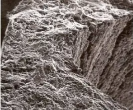
Figure 7 shows the morphology of the crack tip on the outer surface of the piston skirt. The fracture exhibits fatigue bands in the middle and unstable jumping ridge lines in the transient fracture area near the free surface.
Figure 8 illustrates the frontal macromorphology of the sharp corner of the oil hole in the fatigue source area. The macromorphology indicates that there are no original burrs and cracks in the burr at the sharp corner of the oil hole.
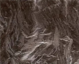
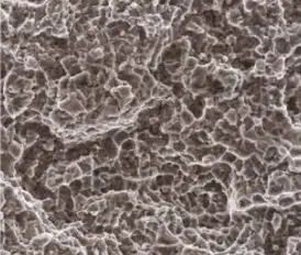
Finally, Figure 9 shows that the fracture extension area is dominated by the cleavage morphology.
(4) The fracture was observed under an optical microscope and the fiber structure was analyzed.
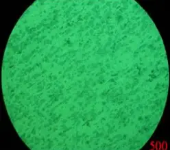
In Figure 10 a photograph of the metallographic sample under an optical microscope is shown. The microstructure consists of α+ (α+ Si) + reinforcement phase and impurity phase, exhibiting a normal microstructure without metallurgical or heat treatment defects.
Figure 11 shows a photograph of the sample in cross section under the scanning electron microscope, revealing that the fracture originates from the sharp corner of the oil hole processing.
Figure 12 illustrates the morphology of the fracture initiation source area, demonstrating that the ripple morphology dominates the final fracture area of the fracture.
3. Results and analysis
(1) Analysis of inspection results
According to chemical composition analysis, the chemical composition of the piston skirt meets the standards of material 4032 in GB/T3190.
The mechanical properties of the piston skirt meet the product design requirements.
The metallographic structure and macrostructure of the piston skirt are normal and no metallurgical, heat treatment or forging defects were detected.
The crack originates from the acute-angled surface formed by the intersection of the piston skirt oil hole and the piston pin hole oil groove.
The crack spreads laterally along the piston skirt and extends from the inside out, indicating a typical fatigue crack.
(2) Analysis of the reason for the failure
After the piston skirt is machined, the oil groove of the oil hole and the piston pin hole form an acute angle. There are still dirty burrs and many original cracks can be seen in the rolled burrs. These cracks cause fatigue and cracking of the piston skirt during operation.
The specific analysis of the cracking process is as follows:
The sharp edge is a stress concentration area, and the small crack is subjected to external forces in the stress concentration area, causing the sharp edge to become a fatigue source area.
The fatigue source area is highly sensitive to notches, and the final notch (crack) extends and propagates under stress concentration, resulting in piston skirt cracking. Therefore, the cracks are fatigue cracks caused by burrs at the sharp corners of the oil holes.
In the actual production process, we must inspect parts for holes, cracks, burrs and other defects on the surface of the piston skirt before the start of each process such as forging, heat treatment, machining and assembly.
If any defects are found, they must be cleaned before starting the next process. This will help avoid discarding parts due to expanding defects in production or subsequent use.