1. Preface
Gas nitriding has several advantages over ion nitriding, including ease of operation, high process repeatability, simple equipment structure, and the ability to achieve automatic process control.
One of the most significant benefits of gas nitriding is the improvement in temperature and uniformity of the atmosphere during the process.
In particular, the depth of the nitriding layer at the tooth root and pitch circle of small modulus gears is more uniform during gas nitriding compared to ion nitriding.
In recent years, the gas nitriding process has seen significant advances, such as the development of pre-oxidation and gas nitriding processes and several other gas nitriding techniques.
These advances have reduced the production cycle time between ionic nitriding and gaseous nitriding by several degrees.
However, it is essential to pay attention to possible problems during the process of controlling the atmosphere during gear nitriding.
2. Cleaning before gas nitriding
Before undergoing nitriding and gas charging, the gear must be thoroughly cleaned to ensure there is no water or impurities present.
If this step is not completed correctly, the resulting nitrided surface may appear uneven and dark spots may appear.
Although there is no significant difference in nitrided layer depth, hardness, or metallographic structure between tarnished areas and normal areas, these tarnishes can significantly impact the overall appearance quality of the gear.
The macromorphology of these irregular punctate areas was analyzed using an ultra-depth-of-field stereomicroscope (as seen in Figure 1).
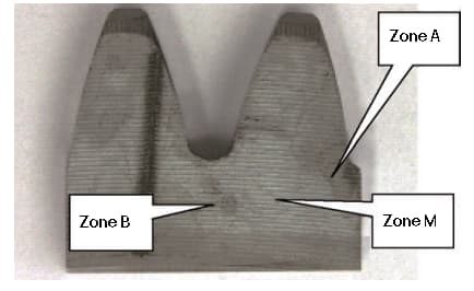
Fig. 1 Macro morphology of the stain area of the gear end face
The microscopic morphology of the stained area was analyzed using a scanning electron microscope (as seen in Figure 2). Areas that appeared white to the naked eye were observed under a scanning electron microscope.
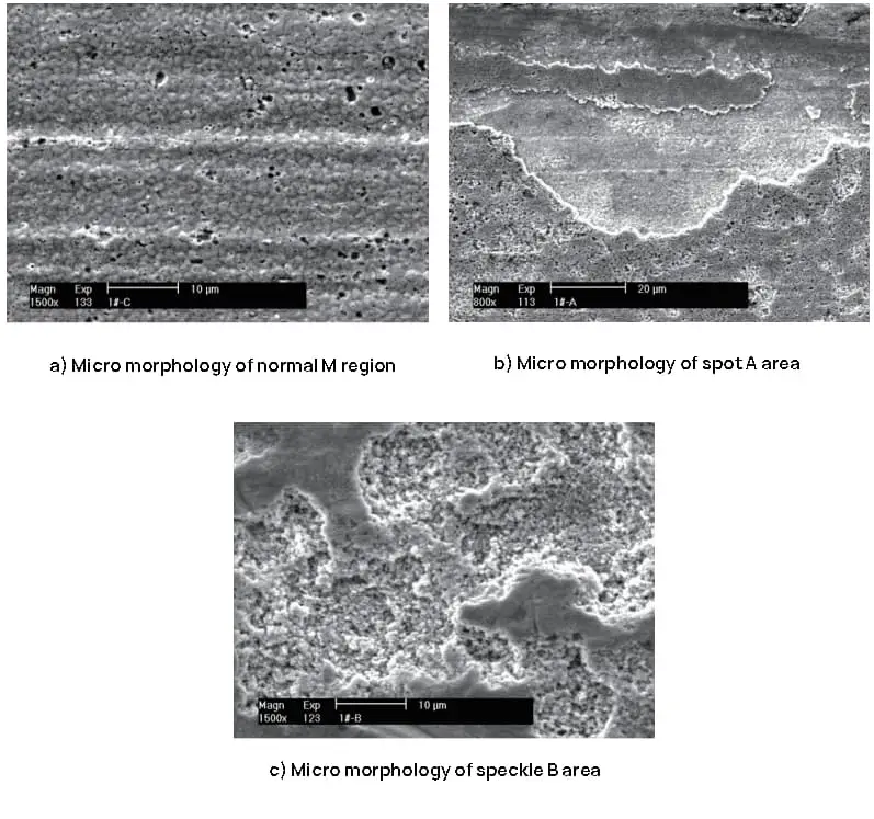
Fig. 2 Micromorphology of the stain area of the gear end face
The chemical composition of the abnormally appearing stained area on the gear end face was compared and analyzed with the normal area on the gear end face. The results of this comparison are presented in Table 1.
Table 1 comparison results (mass fraction) (%) of determining the chemical composition in the microarea of the gear end face
| Detection location: | W | N | O | N/A | Al | Yes | P | s | W | K | Here | Cr | Mn | Faith | |
| Zone M | Normal surface | 0.22 | 0.98 | – | – | – | 0.26 | – | – | – | – | – | 0.19 | 0.63 | 97.72 |
| 0.21 | 0.99 | – | – | – | 0.24 | – | – | – | – | – | 0.25 | 0.57 | 97.73 | ||
| Zone A | White spot surface | 0.43 | 1.03 | 2.91 | – | – | 0.22 | – | – | – | 0.09 | 0.21 | 0.19 | 0.35 | 94.59 |
| 0.38 | 0.89 | 2.58 | – | 0.07 | 0.18 | 0.05 | 0.11 | 0.08 | 0.10 | 0.25 | 0.12 | 0.31 | 94.86 | ||
| Peeling flat bottom | 0.28 | 0.73 | 8.59 | – | 0.09 | 0.56 | 0.04 | 0.08 | 0.10 | 0.12 | 0.06 | 0.33 | 1.40 | 89.61 | |
| 0.39 | 0.84 | 11:59 | 0.15 | 0.10 | 0.67 | 0.13 | 0.11 | 0.09 | 0.12 | 0.06 | 0.34 | 1.71 | 83.71 | ||
| Zone B | Dark spots | 1.03 | 0.58 | 29.53 | 0.50 | 0.10 | 0.51 | 0.05 | 0.90 | 0.39 | 1.21 | 0.18 | 0.26 | 0.51 | 64.25 |
| 0.80 | 0.55 | 28.27 | 0.38 | 0.04 | 0.53 | 0.07 | 1.04 | 0.36 | 1.33 | 0.11 | 0.20 | 0.50 | 65.84 | ||
| White round spot | 0.62 | 0.83 | 3.29 | 0.25 | 0.16 | 0.39 | 0.10 | 0.15 | 0.20 | 0.22 | 0.60 | 0.29 | 0.58 | 92.33 | |
| 0.96 | 0.66 | 5.05 | 030 | 0.16 | 0.60 | 0.06 | 0.14 | 0.23 | 0:30 | 0.96 | 0.32 | 1.09 | 89.16 | ||
As seen in Table 1, the content of element O in the abnormal stained area is higher than that in the normal area. In addition to a higher O content, it also contains traces of Na, S, Cl, K, Ca, Mg, Al and other elements from waste water, cleaning agents and shaving oil.
This analysis shows that the appearance of gas nitriding is caused by poor cleaning before the nitriding process. Therefore, the following points should be given special attention when cleaning gas nitriding gears:
- When using a water-based cleaning agent, the water temperature for the final rinse should not be too high. If the water temperature is too high, it will evaporate quickly and leave residue on the surface of the workpiece. It is best to reduce the rinsing temperature and use a high-pressure air gun to dry the workpiece.
- Cleaning with substances such as acetone or gasoline is possible, but these substances have a low flash point. It is important to ensure adequate ventilation and fire safety in the cleaning environment.
- The workpiece must be completely dried before cleaning with a hydrocarbon cleaner.
- The quality of the water used in the cleaning process must be considered, and pure water should be used as much as possible.
3. Gear nitriding distortion control
The distortion that occurs during gear nitriding is influenced by several factors, including gear shape, machining residual stress, gear material, nitriding tools, nitriding process, and gear cooling speed after nitriding.
In typical production, people tend to focus on the first factors, but often ignore the cooling speed of the gear after nitriding. This is especially relevant for the inner bore of thin-walled gears, which are particularly sensitive to the cooling rate after nitriding.
For example, consider the gear shown in Figure 3.

Fig. 3 gear size
The size of the inner hole before nitriding was φ 52-0.02-0.035 mm. Table 2 presents the relationship between gear cooling time and internal hole expansion.
Table 2 Relationship between gear cooling time and internal hole expansion
| Cooling time after nitriding /H |
Inner hole expansion / mm |
Pass rate (%) |
Comments |
| ≥6 | 0.012~0.021 | 75 | Inner hole size exceeds upper tolerance |
| 4~5 | 0.008~0.012 | 99 | The inner hole is basically within the size range |
| ≤4 | 0.005~0.01 | 78 | Inner hole size out of tolerance |
Test results show that the distortion tendency of gear internal holes at different cooling speeds is consistent and generally increases, but the extent of distortion varies. When the cooling rate after nitriding is slow, the distortion of the inner hole is greater, and when the cooling rate after nitriding is fast, the distortion of the inner hole is smaller.
To ensure stable distortion of the gear inner hole and improve the qualification rate of the gear inner hole after nitriding, the cooling speed of the gear during gas nitriding must be carefully controlled.
4. Remedy for oxidation caused by gas leakage from gas nitriding furnace
If a gas leak occurs in the gas nitriding furnace due to sealing or other problems, the surface of the part will become oxidized. This oxidation does not affect the internal quality of the piece, but does not meet appearance quality standards. In such a situation, the reduction process described in Table 3 can be used for repair.
Table 3 Repair process for oxidized parts
| Repair Temperature /℃ |
Repair time /min |
Ammonia decomposition rate (%) |
| 480~500 | 30~40 | 30~40 |
The appearance of the gear after gas nitriding, oxidation and gas leak reduction is shown in Figure 4.
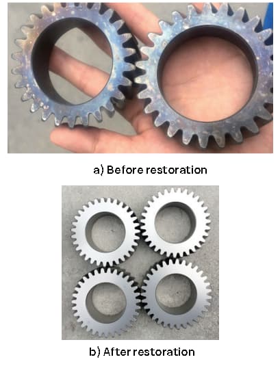
Fig. 4 Appearance of gears before and after ammonia gas leak reduction
It is important to note that during the appearance reduction process, the nitriding temperature should not exceed the first nitriding temperature. Typically, the nitriding temperature during reduction should be about 20°C lower than the last nitriding temperature. The duration of the reduction process can be adjusted based on the extent of oxidation.
5. Conclusion
The above three problems and solutions highlight the importance of paying attention to every detail in the heat treatment process. With careful consideration of each step, you can effectively resolve any issues that may arise.