1. Overview:
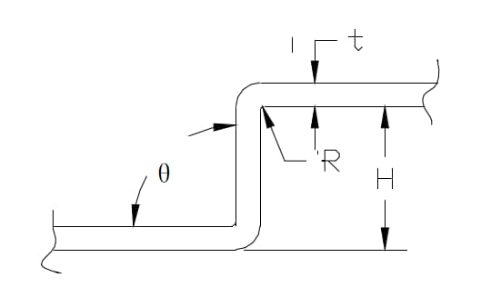
This product, shown in the figure below, is composed of a mold body and a pad, which can create increases and decreases in displacements, and realize forward decreasing segment bending.

The main component pad is fixed with screws, and the pad thickness can be changed or the pad angles can be changed and the offset will change.
2. Patterns:
The maximum applicable plate thickness is SPCC-2.3t.
The range of displacements that can be produced is H=1~10MM.
2.1) Mold displacement is determined by pad assembly and component angle. For information on mold offset, pad assembly, and component chamfer amount, see Table 1.
| Component | Chamfered shim | 0 | 1.4 | 2.9 | 4.3 | 4.9 | 7.8 | 9.2 |
| 0.5 | 6.72 | 5.92 | 5.06 | 4.26 | 3.91 | 2.25 | 1.14 | |
| 1.0 | 7:15 am | 6.33 | 5.47 | 4.66 | 4.32 | 2.66 | 1.85 | |
| 2.0 | 7.95 | 7:15 am | 6.28 | 5.48 | 5.14 | 3.48 | 2.67 | |
| 4.0 | 9.58 | 8.79 | 7.93 | 7.12 | 6.78 | 5.11 | 4.31 |
Formula for calculating displacement height:
Offset height = {11.0-(shim thickness)}×0.574 + (amount of chamfer)×0.819
However, the displacement of the product is equal to the displacement of the mold. The exact amount of displacement from the mold to the product is confirmed through experimental bending of each product, with both correct and erroneous results.
2.2) If the displacement H is small, the angle θ will increase.
2.3) The radius of curvature R is generally less than or equal to R2. If the displacement H is small, the angle R will also decrease.
2.4) The pad is classified as third class accessory, with 2 pieces each for 1.4t, 2.9t and 4.9t, and combined with the chamfered component.
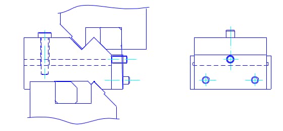
3. Methods for adjusting the mold using an adjusting pin
1)First, install the upper mold; After placing the lower mold on the lower mold installation seat, adjust it using the adjusting pin.
2)If the displacement is relatively small (around H=1~2mm), the mold can also be calibrated directly by combining the upper and lower molds.
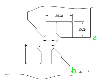
3)Adjustment pin scale adjustment method:
(1) When adjusting dimension A, the offset may vary due to differences in plate thickness or bend shape and cannot be generalized. This is just an approximate adjustment range: A = V/3 + 0.245t;
(2) Measure the vertical distance between points a and b, and the vertical distance between the two ends of the mold must be equal.
4) Precautions when using the Adjustment Pin tool:
4)-1 First, match the chamfer and shim according to the offset height, and install the upper and lower molds, but do not fix the lower mold first.
4)-2 The adjustment pin adjustment must be consistent with (0.245t) and the corresponding plate thickness. After adjustment to the corresponding scale, all screws must be tightened.
4)-3 As shown in the figure below, place two symmetrical adjusting pins on the lower mold, align them with the upper mold, and press down to about 1 ton or less. After fixing the lower mold, remove the accessory.
4)-4 Dimension A shown in the figure above can theoretically change due to the displacement and thickness of the plate. As this accessory automatically sets the displacement, only the plate thickness can be adjusted according to A = 0.245t. There are theoretical data and actual bending tests, and the best angle should be obtained (especially for bending with different plate thicknesses or blunt angle bending, etc.).
Warning: Do not use more than the specified compressive strength of the mold;
If any damage to the mold is found, stop using it immediately.
The mold must be installed strictly in accordance with operating procedures.