The structure of a bending die varies depending on the characteristics of the bent part (shape, size, level of precision, etc.) and the production volume. The complexity varies and there are countless forms. Here, we only briefly introduce some common structures of bending matrices.
1. V-shaped bending die
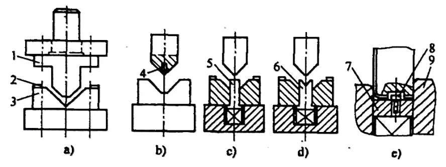
There are many forms of commonly used V-shaped bending die structures, as shown in Figure 2-23.

- 1 – Punch
- 2 – Positioning Plate
- 3 – Die
- 4 – Positioning Pin
- 5 – Ejector Rod
- 6 – V-Shaped Ejector Plate
- 7 – Ejector Plate
- 8 – Positioning Pin
- 9 – Counter-recoil.
1) The structure shown in Figure 2-23a is a common V (or L)-shaped part bending mold structure. Its characteristics are simplicity and versatility, but with lower efficiency and precision.
2) The structures shown in Figures 2-23b to 2-23d are bending die structures with positioning pins, ejector rods and V-shaped ejector plates. Their characteristic is that they can prevent the part from moving during bending, improving the precision of bent parts.
3) The structure shown in Figure 2-23e is a flexible matrix structure with positioning pins and an ejector plate. It can effectively prevent the workpiece from shifting during bending, improving the accuracy of bent parts, and is capable of processing bent parts with a side length tolerance of 0.1.
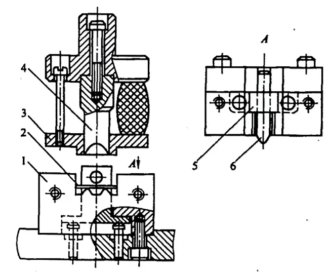
4) Figure 2-24 shows a V-shaped bending die structure with a hinged plate. Its working principle is: The two parts of the die are connected to each other by a dumpling chain and inserted into the pivot of the two pillars, keeping the center vertical, and bending the piece together with the die. When the punch retracts, the die rotates and returns to its starting position with the help of the damper ejector rod below.
Its characteristic is: During the bending process, the sheet metal part is always in contact with the rotating die, suitable for bending operations that do not have sufficient supporting area for pressing and are narrow and long.
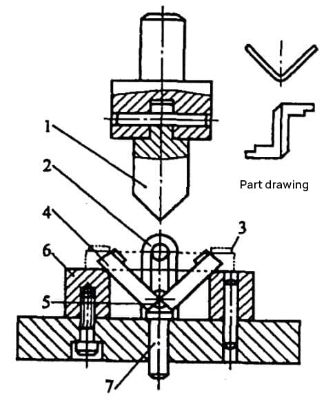
- 1 – Punch
- 2 – Pillar
- 3 – Positioning Plate
- 4 – Turn the dice
- 5 – Dumpling Chain
- 6 – Counter-recoil
- 7 – Ejector Rod.
2. U-shaped bending die
According to the various requirements of U-shaped components, the commonly adopted bending die structures are illustrated in Figures 2-25 and 2-26. A brief introduction to its applications and features is provided below.
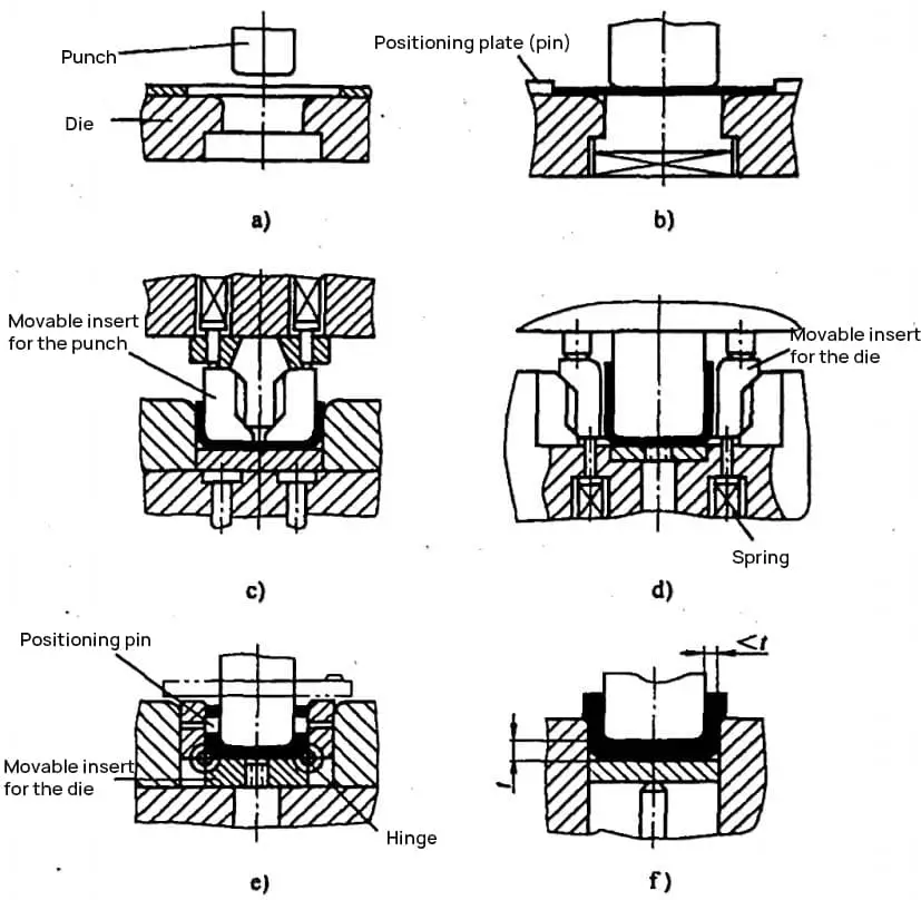
4) The structure shown in Figure 2-25d is used for components with higher internal dimensional requirements. When the thickness tolerance of the blank is large, the sides of the punch are transformed into movable inserts. Under the action of the spring, the punch width can be automatically adjusted according to the thickness of the material.
5) The structure shown in Figure 2-25 is used for components that require coaxial holes on both sides. Movable inserts on both sides of the die have locating pins for positioning the blank. As the punch descends, it presses the blank and movable inserts into the die, ensuring coaxiality of the holes on both sides.
When the punch rises, the movable die and pressure plate return to the top of the die under the action of the spring. The disadvantage is its complex structure and difficulty in manufacturing.
6) The structure shown in Figure 2-25f is for parts with thin sidewalls.
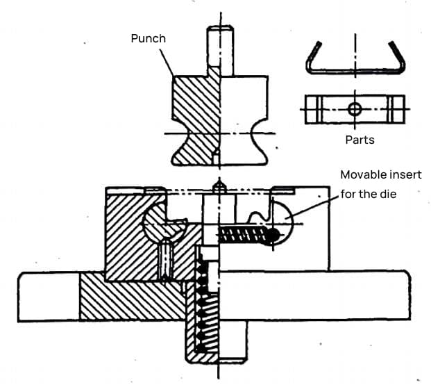
7) The structure shown in Figure 2-26 is used to bend U-shaped components with angles φ<90°. Movable inserts on both sides of the die can rotate within the cavity. During press bending, the punch first bends the part into a U shape.
As the punch continues to descend, movable inserts on both sides of the die rotate and bend the blank into the U-shaped component to the desired angle φ<90°. When the punch rises, the movable insert is reset under the action of the spring, and the punch carries the workpiece out of the die, and the workpiece is discharged from the punch along the Z axis direction.
Related Reading: V and U Shaped Bending Strength Calculator
3. Z-shaped bending die
When the step height H is within 2t
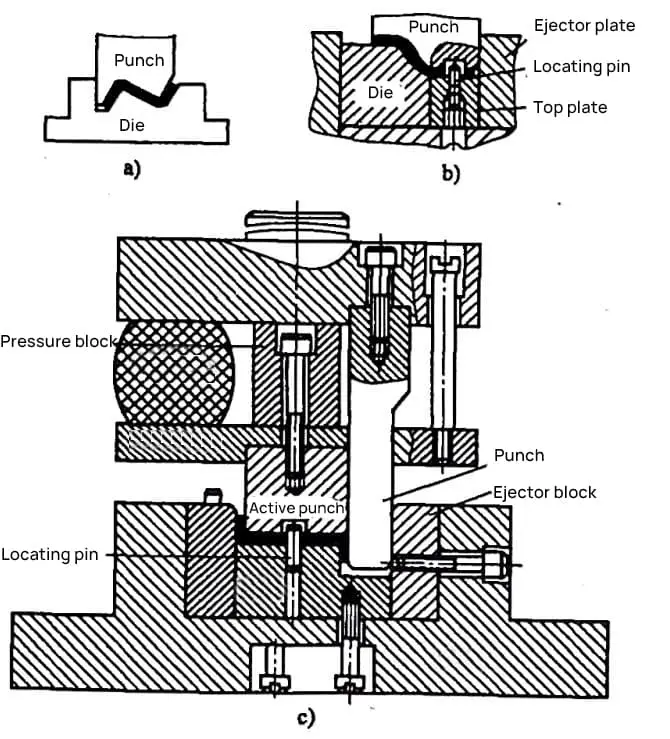
1) The structure shown in Figure 2-27a is simple. However, without a pressing device, the blank can easily slip during press bending. It is only suitable for parts with low precision requirements.
2) Figure 2-27b shows a Z-shaped (step) bending mold structure with a top plate and a locating pin, which effectively prevents the blank from sliding and shifting during the press bending process, thus improving the machining precision of the parts.
3) Before the bending of the press begins in the structure shown in Figure 2-27c, the movable punch and punch are leveled at the top under the force of a rubber sheet. As the press bending begins, the movable punch and top plate clamp the blank, and under the action of the force of the rubber sheet (>spring force of the top plate), the movable punch and top plate move down, causing the left side of the blank to come loose. to bend.
When the upper plate comes into contact with the lower base of the mold, the force of the upper plate increases, compressing the rubber sheet. The punch moves down, bending the right side of the shaped part. When the upper base of the mold comes into contact with the pressure block, the part is checked and corrected. This structure can produce high-precision parts, but it is complex and difficult to manufacture.
4. Four Corner Bending Mold
Parts bent at four corners can be formed in one or two steps.
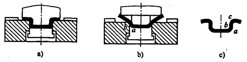
1) The structure of the one-step four-corner simple bending mold is shown in Figure 2-28. When bending parts with this mold structure, inaccuracies in the shape of the outer corner and thinning of straight wall sections often arise (especially when the material thickness is t>1~1.5mm and its straight wall part is relatively high ).
This can be seen in the molding process shown in Figure 2-28b. When the male mold goes down, the inner corner folds it into a fixed fold line position. However, the position of the outer corner fold line is not fixed, first at point b and finally at point c.
Therefore, the final part obtained has the shape shown in Figure 2-28c, and the straight wall section tends to become thinner due to the tensile force during bending. Because this flexible mold structure is simple and easy to manufacture, it can be used when the parts requirements are not high and the production volume is not large.
2) Figure 2-29 shows the structure of a four-corner, two-step bending mold. This structure ensures that the inner and outer corners bend at the bend line, thus avoiding the thinning phenomenon shown in Figure 2-28c and improving the quality of the bent parts. However, this mold has a low production efficiency and can only guarantee sufficient strength of the concave mold when the height H of the bent parts (see Figure 2-29b) is >(12~15)t.
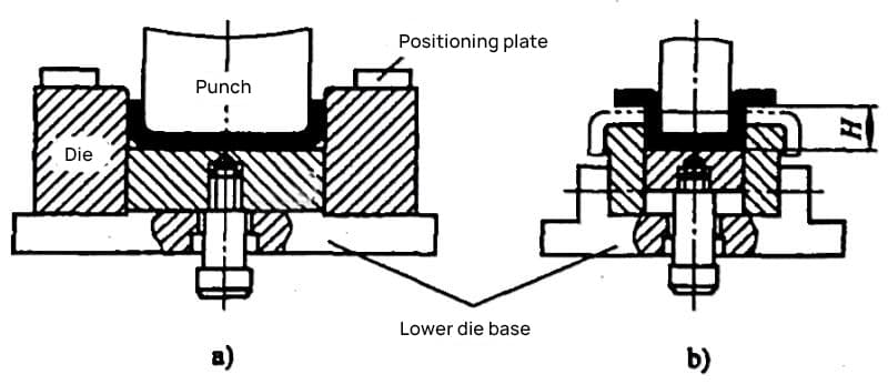
- a) Step 1
- b) Step 2
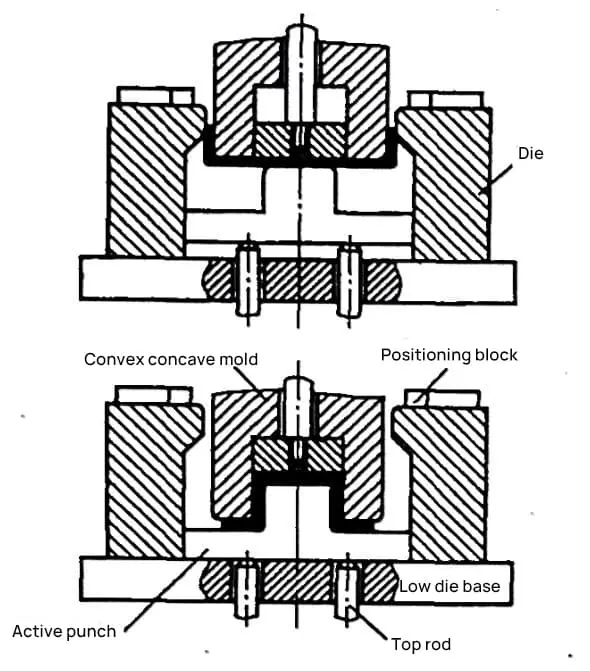
3) Figure 2-30 shows the structure of a bending mold composed of two stages. This structure ensures that the inner and outer corners bend at the fold line, thus avoiding the bending deformation phenomenon shown in Figure 2-28. As the convex and concave molds descend, the blank is first bent into a U-shape by the concave mold (convex-concave mold thrust force > active convex mold ejection force).
When the active convex mold contacts the lower mold base (active convex mold ejection force > convex-concave mold thrust force), the convex-concave mold continues to descend, and the active convex mold finally shapes the part bending it. The disadvantage of this bending mold is that it requires a large cavity space in the bottom mold to facilitate lateral forming of the part.
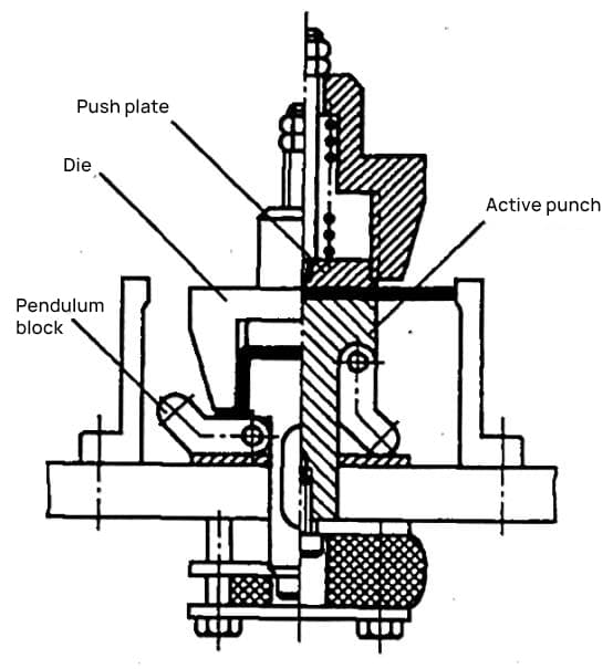
4) Figure 2-31 shows another structure of a bending mold composed of two stages (with oscillating block). As the concave mold descends, the blank is first bent into a U-shape by the ejection force of the active convex mold. The concave mold continues to descend and when it comes into contact with the top of the top plate, it forces the convex mold to descend and the rocker block to rotate to the side.
Under the force of the oscillating block, the part is finally shaped by bending. The disadvantage of this composite bending mold is the complexity of the mold structure.
5. Bending mold for cylindrical parts
The bending method for cylindrical parts is typically determined by the diameter of the cylinder. For cylinders with a diameter (d) smaller than 5mm, small circular bending is considered. For cylinders with diameter (d) equal to or greater than 20mm, it is categorized as great circle bending.
(1) Bending of small circular parts with a diameter (d) of less than 5 mm
The bending process for small cylindrical parts involves first bending into a U-shape and then bending that U-shape into a cylindrical formation. This is done by using two pairs of simple bending dies to form a cylinder, as shown in Figure 2-32.
Due to the small size of the workpiece, it is inconvenient to perform the bending operation twice, so the two steps can be combined or a step bending mold can be used for shaping. Figure 2-33 shows a one-step bending mold for small cylindrical parts.
When the upper mold goes down, the pressure plate presses the slider down. Sinking dictates that the central rod billet is first bent into a U-shape. As the upper mold continues to descend, the convex mold bends the U-shape into a cylindrical shape. This structure is suitable for soft materials and bending of small and medium diameter cylindrical parts.
- a) First step: Fold into a U shape
- b) Second step: Fold into cylindrical shape
- 1 – Concave mold
- 2 – Sheet material
- 3 – Pressure plate
- 4 – Convex mold
- 5 – Slider
- 6 – Central rod
(2) Bending of large circular parts with a diameter (d) equal to or greater than 20 mm
Figure 2-34 shows a one-step bending mold for large cylindrical parts with an oscillating concave mold. As the convex mold descends, it initially forms the U-shaped part. As the convex mold continues to descend, the oscillating concave mold bends the U-shape into a circular shape.
The part can be removed by pushing the holder along the convex axis direction of the mold. This mold has a relatively high production rate, but due to rebound, there are gaps and a small amount of straight edge left at the seam of the part, resulting in poor part precision and a more complex mold structure. Figure 2-35 shows a two-step bending method for large cylindrical parts.
First, it is pre-bent into three 120° waves, then it is folded into a circular shape using the second pair of dies. The part is removed in the direction of the convex axis of the mold. Figure 2-36 shows a three-step bending method for large cylindrical parts, which has a lower production rate and is suitable for parts with greater material thickness.
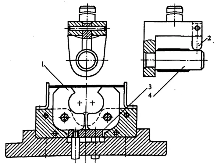
- 1 – Oscillating concave mold
- 2 – Convex mold support
- 3 – Top plate
- 4 – Convex mold
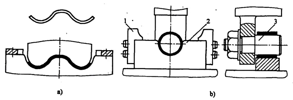
- a) The initial curvature forms a 120° wave.
- b) The second curve presents: 1 – a positioning plate, 2 – a male matrix, 3 – a female matrix.
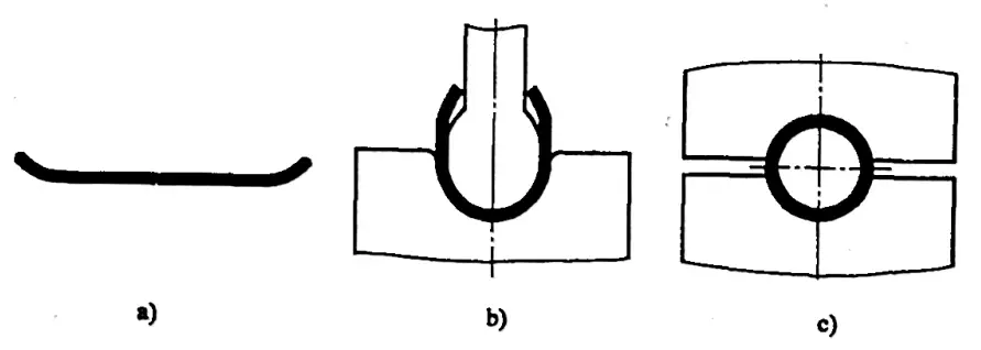
- a) First flexion
- b) Second flexion
- c) Third push-up
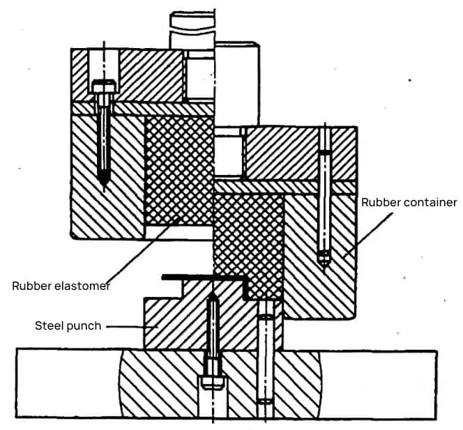
6. Rubber Bending Mold
The rubber bending mold replaces the concave part of the bending mold with rubber, while the convex part still uses a steel mold, as shown in Figure 2-37. Rubber can transmit pressure in all directions like a liquid inside a sealed container. Compared with rigid bending molds, the bending process undergoes advantageous changes. Rubber or high hardness elastomers (60-80AS) produce better results.
The processed bent parts not only feature high precision and have no surface scratches, but the universal nature of the rubber or elastomeric concave mold is also excellent. It is best suited for processing single and small batch parts with high bend size accuracy and surface quality requirements, as well as parts made from softer materials.
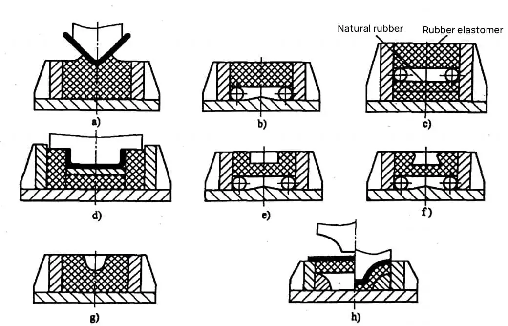
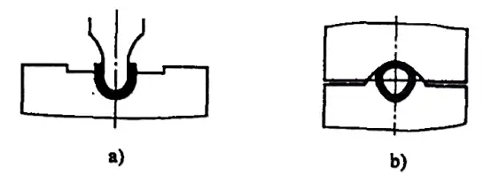
Figure 2-38 shows various concave container structures of common rubber bending molds and bending methods.
Figure 2-38a is suitable for bending V-shaped parts with small radii.
Figure 2-38b is suitable for bending U-shaped parts and V-shaped parts with smaller radii.
Figure 2-38c is suitable for bending V-shaped parts with larger radii, forming an open formation.
Figure 2-38d is suitable for bending U-shaped parts.
Figures 2-38e, f, g, h are respectively suitable for bending ring-shaped parts or special-shaped parts with wings on both sides, forming joints.