The punch is one of the most important components of stamping dies, which includes various indicators such as structure, installation, processing, material and cost in its design.
Designing the punch correctly, effectively, reasonably and economically can not only improve the die life, reduce manufacturing costs and increase production capacity, but also facilitate processing and maintenance, making subsequent stamping production efficient and smooth.
The matrix is known as the mother of the industry and is the basis for ensuring manufacturing precision and quality. Germany and Japan evaluate very well the role and importance of matrices in industry and the economy.
In 2002, due to inadequate technology from a European supplier of molds for computer connector terminals, Intel produced unqualified parts, allowing a Taiwanese-funded company in Shenzhen to use 11 high-speed punching machines to produce the terminal day and night during several months, with a monthly production value exceeding NT$1 billion. This was a miracle for a factory with over 3,000 employees.
Today, the application of continuous precision stamping dies in modern parts production is increasing and their importance is becoming more prominent. Precision stamping of thin materials is a necessary process for the production of modern electronic parts, and its punch design is particularly important.
Punch Design
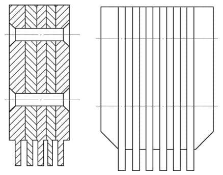
1. Types of punch structure
The structure of punches can be divided into two types: insert and integral. The insert type combines several small punches, but its assembly error is relatively large and inconvenient for maintenance, so it is less used in modern high-speed stamping dies.

The integral punch has four main types of structure:
Shoulder punch (see Figure 2):
It was widely used in the past, with large cutting edge size and straight type at the bottom. The shoulder is designed to prevent the punch from being pulled away from the fixed plate during unloading. The shoulder is designed asymmetrically to avoid installation errors.
However, the projection makes disassembly and maintenance inconvenient, as the punch can only be removed by disassembling the mold, which would seriously affect the accuracy of the mold.
Direct puncture (see Figure 3):
This type of punch has a large cutting edge and is an improvement on the shoulder type punch. It no longer has a shoulder and the cutting edge has the same shape and size as the fixed part. This improvement increases the application rate of direct punctures.
Reinforced punch (see Figure 4):
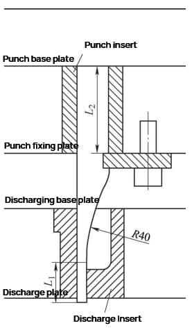
With the increasing precision of modern die production, the size of the cutting edge at the bottom becomes smaller, and the rigidity and strength of the direct punch are poor. In the past, perforated sleeves were often added.
To improve the rigidity and strength of the punch, a straight section L1 (6-10mm) is designed at the bottom, and the middle is reinforced with an arc R40mm (minimum radius of the optical grinding wheel).
The installation top is designed as a rectangle for easy maintenance and moving. As there is a groove for the pressure plate to prevent misalignment, no additional anti-misalignment structure is required.
When designing, it is best to place the cutting edge close to the sides of the reinforced punch for easy installation and positioning, reducing processing difficulty and cost. Reinforced punches are currently the most commonly used punch structure.
Round punch (see Figure 5):
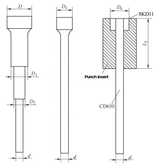
The round punch is widely used and almost all die sets use it. When the diameter of the punch is very small, it is difficult to manufacture multi-axis cam punches and single-axis cam punches.
The adhesive head punch cuts the small diameter punch material (CD650) to the required length and uses an alloy steel mold (SKD11) to make a sleeve out of the installation part.
The two are joined with anaerobic adhesive, resulting in the same effect as a single-axis round shoulder punch, but at a cost of less than 1/3. Because the round punch is not conducive to displacement during maintenance, a rectangular punch insert is often designed and placed in the punch.
2. Fixed punch installation methods
The installation of the punch die is carried out on the fixed plate of the punch die, which has both positioning and fixing requirements. Positioning of the punch die is achieved by combining the punch die and the holes in the fixed plate.
Fixation can be carried out using hanging shoulders, screws, rivets, epoxy resin glue, side pins, horizontal pins and pressure plates.
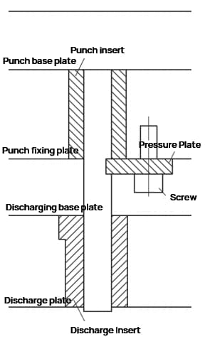
For a straight punch die, due to its irregular shape, an auxiliary rectangular punch die insert needs to be added to the installation position.
The fixed plate has a certain distance between the fixed position of the punch die and the working position of the edge of the punch die, which can easily cause the punch die to become unstable and fail.
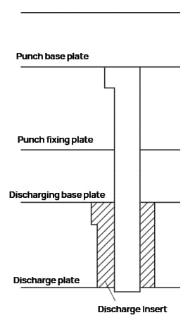
If the edge size of the punch is small, normal production will be impossible. When the punch die is turned into a pressure plate for clamping, a discharge insert must be added. When the punch die passes through the discharge insert to perform punching with the die, the discharge insert can guide the punch die into the die to protect the punch die against lateral forces.
The design one-sided clearance between the punch die and the discharge insert is 0.003-0.005mm or even smaller. When the punch die is working, the discharge insert is exposed about 3mm, which is not easily damaged. The size of the punch die installation position is designed to be equal to or slightly smaller than the size of the square hole in the fixed plate.
The pressure plate groove is 0.02-0.05mm lower than the fixed plate, allowing the punch die some room for movement within the fixed plate. The actual positioning depends on the discharge insert, avoiding interference between the fixed plate and the discharge insert.
As the positioning point of the discharge insert is the working position of the punch die edge, the effect is ideal. Remove the pressure plate screws and remove the pressure plate to remove the punch die.
Disassembly of the punch die is convenient, allowing quick maintenance and repair of the punch die.
3. Selection of material for drilling die
The punch die must be able to withstand a certain amount of impact force and at the same time have high wear resistance.
Therefore, a high hardness material with certain toughness should be selected. For continuous precision stamping dies, material selection for the punch die is even more critical to meet your mass production capacity.
Traditional punch die materials such as Cr12MoV, Cr12 and SKD11 can only be used to make templates or inserts in continuous precision stamping dies.
The most commonly used material for punch dies in continuous precision stamping dies is CD650 tungsten steel material, which has a high surface quality, is extremely wear-resistant and has a maximum hardness of 90HRA.
The second most commonly used material is foreign high chromium molybdenum vanadium powder material ASP-23, with the best hardness around 63HRC.
4. Processing methods for perforated die
The irregular shape of direct punching dies is usually processed by slow wire cutting, with one cut and one or two repairs.
Although slow wire cutting has high processing accuracy, the thin oxide layer generated on the surface at high temperatures can also affect it, resulting in a dimensional accuracy of ±0.003 mm.
Hanging shoulder punch dies are processed using a common small surface grinder (G), and attention should be paid to designing the hanging shoulder in a location that does not affect processing.
The reinforced punch dies are processed on an optical grinding machine (PG), which is more expensive. The latter two processing methods can achieve a dimensional accuracy of ±0.002 mm.
Conclusion
Continuous precision stamping dies have high requirements for die life. The life of stamping dies of small electronic and communication hardware typically needs to reach 100kk (100 million) strokes, while the life of terminal dies needs to reach 500kk (500 million) strokes.
When designing the punch die, various factors such as product accuracy, production targets, die life, processing difficulty, ease of maintenance and economic performance must be comprehensively considered.
By designing the punch die correctly, reasonably and flexibly according to the actual situation, it can meet product quality requirements, facilitate timely improvements, and ensure smooth production.