The arrangement of blind parts in sheet metal, strip or strip material is called layout. Layout efficiency directly affects material utilization, part quality, cost, die structure and service life. The careful selection of materials is significant in saving materials in printing production.
An effective layout is a robust measure for material conservation, especially in mass production where material costs account for a large proportion. Full utilization of materials is a crucial economic indicator in the production of sheet metal parts.
Comprehensive consideration must be given during the layout process, and all factors that impact the layout must be analyzed to establish the best layout plan.
There are three classification methods for blind part layout. The layout from the perspective of waste is divided into: layout with waste, layout with less waste and layout without waste.
1. Layout with Waste
The wasteful layout (see Fig. 3-10) is around the entire perimeter of the part. As there are overlaps in the material, the quality of the blank parts is guaranteed and the service life of the die is long. However, material utilization is low.
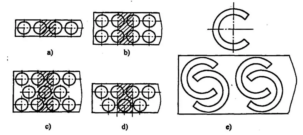
- a) Single round piece layout
- b) Parallel double round part layout
- c) Triple crossed round part layout
- d) Double cross round part layout
- e) Cross layout
2. Layout with Less Waste
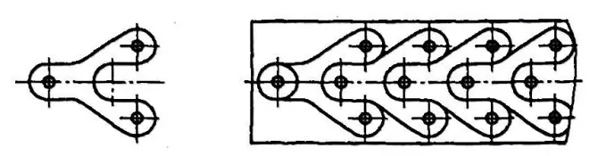
The least wasteful layout (see Figure 3-11) is done along part of the outer shape of the part, leaving overlap or excess material only in specific areas.
3. Waste-free layout
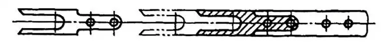
Waste-free layout (see Figure 3-12) refers to a layout with no process waste (overlap and excess material), only structural waste determined by the structural shape of the part (such as waste in holes).
From the above analysis, it can be seen that, as long as it does not affect the usage requirements of the parts, adopting a layout with less or no waste can increase material utilization to 75%-95%. This is beneficial not only for stamping multiple parts at once, but also simplifies the die structure and reduces cutting force.
However, due to the influence of the dimensional tolerance of the strip itself and the errors caused by the orientation and positioning of the strip, the quality and accuracy of blind parts are inferior.
Meanwhile, as the die experiences one-sided force, it aggravates the wear of the die, reduces its service life, and directly affects the cross-sectional quality of the blank. Therefore, the layout must be coordinated and fully considered.
The second method categorizes the layout methods of blind parts according to the shape of the workpiece and the layout method into: straight layout, diagonal layout, straight opposite layout, opposite diagonal layout, mixed layout, multi-row layout, etc. ., as shown in Table 3-5.
Table 3-5 Layout Methods
| Default Layout Types | Material Dimensional Layout | Minimal or non-dimensional material layout | |
| Vertical arrangement |
|
|
|
| Diagonal Arrangement |
|
|
|
| Direct Opposition Agreement |
|
|
|
| Diagonal opposition arrangement |
|
|
|
|
|
|
||
|
|
|
||
| Panel Layout Method | Full Cut Method |
|
|
| Staged cutting technique |
|
||
The third method is the mixed layout method, also known as nesting. This approach is suitable for CNC punching machines (turret punching machines) and laser cutting. When arranging the layout based on the analysis of the types of punched parts in our company, we should adopt the mixed layout method whenever possible for suitable parts.
In conclusion, after ensuring that the key technical requirements of the parts are not affected and with the consent of the product designers, modifying the structural shape of the parts to accommodate minimal or zero waste layouts not only saves a substantial amount of raw material, but It also increases the efficiency of product production.