Modern engineering decision makers consider the use of excessive computing power at this stage to be useless and time-consuming. Applying approximation techniques is much more efficient and helps to reduce the time required to perform parametric modeling. These techniques include Reduced Order Modeling, which reduces the mathematical complexity of the system while ensuring that the physics of the underlying partial differential equations are preserved.
After carrying out the first analysis, an iterative process comes into action in which the results dictate changes to the project for optimization. This process is the link between conception and the preliminary design phase. For more details, see Industrial Design Prototyping.
Let's look at a summarized form of the famous Howe model for the project synthesis process.
- It is an extension of the feasibility study, but includes more details and complexity.
- The first step in this process is to select one or more settings.
- The second phase is known as flight regime and engine selection. At this stage, for a given set of operating conditions, i.e. Mach number, etc., the type of engine to be selected is selected, i.e. turboprop, piston propeller, turbofan, low bypass ratio turbofan, turbojet , ramjet engine, etc.
- The next step concerns the selection of the hull layout. Payload details are often the determining factor for this step. This provides a good starting point for initial aircraft mass prediction.
- Next is the wing configuration. This is a complex procedure for the aerodynamics laboratory, in which a large number of parameters play a role. It is a fundamental phase during the preliminary design process. It results in an initial estimate of an aircraft's lift, drag and mass and also assists in carrying out calculations to estimate wing loading after subsequent analysis has been carried out. Wing loading is estimated based on theoretical equations adjusted for various flight conditions based on empirical data. It also helps in obtaining a rough estimate of the thrust-to-weight ratio.
- Finally, the phases of parametric analysis come into play. The first phase combines the wing and fuselage dimensions to produce a set of results for each phase of flight. This leads to the formation of a design space. For the second phase of the parametric analysis, appropriate sets of wing loads and thrust-to-weight ratios are selected.
- In the second phase of the parametric analysis, the selected data sets are used to calculate the total mass of the aircraft. The dataset with the ideal mass value is used to create a reference design, which is then used for in-depth analysis and evaluation.
- The arbiter design is evaluated, which in turn results in the following:
- Estimated sizes for control surfaces
- Help finalize the landing gear layout
- Better estimation of lift, drag and mass values
- Revised calculations of performance indicators based on adjusted input data and complex estimation procedures
- The process is repeated until the mass convergence criteria are met.
- At the end of this design phase, sensitivity studies are performed to identify critical design areas using graphical or mathematical techniques. In addition, other activities take place in parallel, including the design of hydraulic, electrical, fire extinguishing, ice protection and pneumatic systems.
The next phase, the detailed design phase, is where the magic happens: the design is fully defined, scale models for testing are ordered from a prototype manufacturer, and then final drawings are created based on the assembly design. and manufacturing with real topologies and geometries. , dimensions, tolerances, and material information created. Now let's discuss this in more detail in the next section.
Detailed project
The focus of this phase is primarily on obtaining verifications for the design procedures described in the previous phases. It is the most extensive phase of the entire design process. She focuses on the final design, prototyping and testing of each part. Based on data obtained in the preliminary design phase, this phase includes the use of computer-aided design and computer-aided manufacturing packages to support design activities.
There are three factors to consider: performance, manufacturing cost, time required and operational efficiency. To achieve a comprehensive result, two types of testing procedures are required: ground testing and flight testing. Let's take a closer look at the distinctive features of both species.
- Ground testing: This includes wind tunnel testing to validate CFD package results, structural testing, avionics evaluations, and systems testing. This is the phase where prototyping comes to the rescue. Prototyping full-scale parts for initial testing is essential to save time and costs. A good prototyping service provider will use the appropriate knowledge to manufacture the structure from the material specifications required by you. The prototype can be used to analyze strength, stiffness, vibration, elastic stability and other system parameters. Static loading, dynamic loading, modal vibration analysis and flutter analysis are some of the important tests to be carried out. For full-scale aircraft parts, stereolithography 3D printing provides the precision needed for a comprehensive evaluation between sketched design and experimental results.
- Flight testing: The involvement of certification bodies to verify the performance and flight characteristics of the actual aircraft. These bodies are called airworthiness authorities. They evaluate an aircraft's design based on the predefined design and safety requirements established in the airworthiness standards of the Federal Aviation Regulations. The table below details all airworthiness standards and their respective applications.
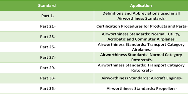
Among the most important standards is FAR Part 23, which applies to normal, multirole, and aerobatic aircraft with a maximum takeoff weight (MTOW) of less than 12,500 pounds and a passenger capacity of 9 people or less. It also prescribes standards for commuter aircraft with an MTOW of 19,000 pounds or less and a passenger capacity of 19 people or less.
For commercial transport category aircraft, such as the Airbus A320 or Boeing 737, FAR Part 25 prescribes the required standards. Part 25 includes several subparts, namely A, B, C, D, E and F, all of which prescribe standards for the various systems and subsystems of a commercial transport aircraft.
Similarly, for helicopters (more commonly known as choppers), Parts 27 and 29 of the FAR set the standards for the normal and transport categories, respectively. Once airworthiness certificates are received, the design cycle effectively ends, with 95% of life cycle costs occurring at this stage. This is followed by the large-scale production phases.
Completing the aircraft design process
This in-depth review of an aircraft design cycle may seem very complex. However, with a step-by-step approach, thoughtful decisions based on critical thinking and wise decision making, the aircraft design cycle is an achievable achievement. In the modern era, where risks are high in terms of cost and time, the use of prototypes when necessary is essential, as the success of an aircraft project depends entirely on the comprehensive validation of design ideas. But it is very important to hire the services of the right aerospace prototype manufacturer as the accuracy of the prototypes is of great importance. Any shortcut taken at any stage of the design cycle later proves destructive, as was recently the case with the Boeing 737 Max.