I . Introduction
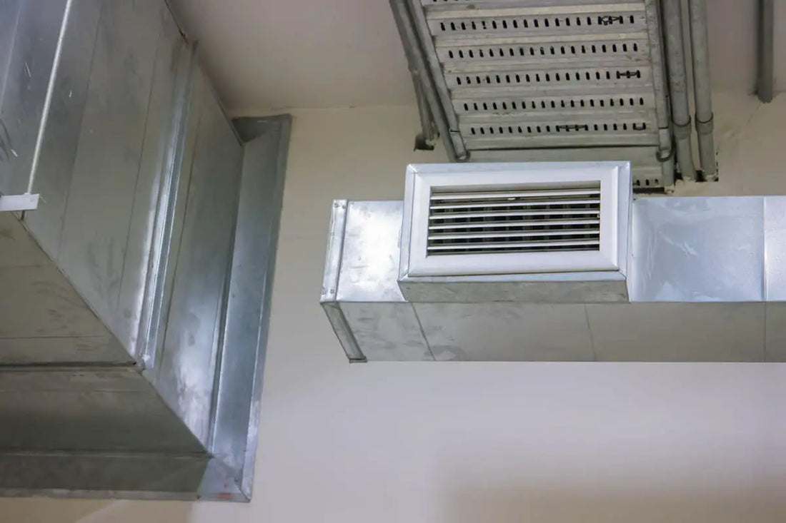
The air duct, as the name suggests, is a piping system used for aerial transportation and distribution.
It can be classified according to cross-sectional shape, material and connection way, etc.
According to the cross-sectional shape, air ducts can be divided into round duct, rectangular duct and oval duct, etc.

Among them, the round duct has the lowest resistance, but the largest height dimension, and is complex to manufacture, therefore the duct with the greatest application is the rectangular duct.
According to the material, the air duct can be divided into metal duct, non-metal duct, composite duct and Nanosox air duct, etc.
According to the connection way, it can be divided into flanged connection duct, flangeless connection duct and spiral duct, etc.
Flangeless connection duct can be divided into thin plate flanged duct, cross duct according to its specific connection way.
Thin sheet flange duct can be divided into combined flange duct and joint flange duct depending on whether its flange and duct are integrated.
Thin sheet flanged duct can be divided into TDC duct and TDF duct according to different flange cross-section shapes.
TDC Duct Meaning:
TDC or Cross Duct Connection refers to a specific type of flange system used in HVAC installations to connect ductwork. It is preferred for its efficiency, strength, and leak-resistant qualities, making it ideal for high-performance air systems.
TDF Duct Meaning:
TDF, or Transverse Duct Flange, refers to a type of duct connection system in HVAC (heating, ventilation and air conditioning) applications. It is known for providing airtight seals and easy installation due to its incorporated flange and gasket design.
Thin plate joint flange duct, commonly known as TDC/TDF duct, was invented by Lockformer Company in 1982.
TDC and TDF are two types of duct flange systems used in HVAC. The TDC (Transverse Duct Connector) is known for its robustness and rigidity, making it ideal for large pipelines. TDF (Transverse Duct Flange) is lighter, easier to install and more economical, generally preferred for smaller ducts. Both provide secure, airtight connections, but the choice depends on the specific project requirements.
This new duct format began to be used in real projects in developed countries in Europe and the United States in the 19th century. and gradually it has been widely used.
China National Standards Specification for Construction Quality Acceptance of Ventilation and Air-Conditioning Engineering (GB50243-2002) clearly states that rectangular ducts can be used in the form of TDC/TDF ducts.
The subsequently released 07K133 Atlas detailed reference standards for specific TDC/TDF pipeline engineering practices.
Many projects started using TDC/TDF ducts, which had good results.
While effectively improving the production efficiency and quality of air ducts, it also greatly enhances the company's core competitiveness.
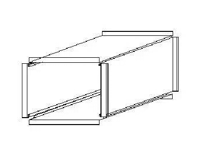
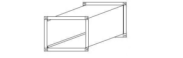
The schematic diagram of the TDC/TDF duct is as follows:

④ The height of the angle iron or reinforcing ribs must be less than or equal to the height of the duct flange, the arrangement must be clean, the gap must be uniform and symmetrical, and the riveting or welding with the duct must be firm.
⑤The inside of the pipe is reinforced with a harness bolt, and its special gasket is placed on the inner wall of the duct for external insulation.
For uninsulated duct or insulated duct, it should be placed on the outer wall of the duct and the threaded screw should be placed in the center of the duct.
When the cross-section of the air pipe is large, a whip screw bracket should be added on both sides near the flange for reinforcement.
⑥ When the duct section is greater than 1250×630, to keep the adjacent walls perpendicular to each other, it is advisable to use 90°C diagonal braces for reinforcement at the four corners of the duct.
⑦ If the length of the medium pressure system air duct is more than 1250mm, it should be reinforced with a reinforcing frame.
⑧ The air duct of the purifying air conditioning system should not be reinforced on the inner wall of the pipe.
The outer wall of the pipe should be reinforced by triangular ribs, Z-shaped grooves and steel angles, etc.
⑨ The degree of reinforcement and rigidity of the air duct must meet the requirements of Technical Regulation for Ventilation Ducts (JGJ141-2004).
The following tables show specific regulations:
Rectangular duct reinforced stiffness degree
| Types of reinforcement | Reinforcement specifications (mm) | Reinforcement height(mm) | |||||
| 15 | 25 | 30 | 40 | ||||
| degree of rigidity | |||||||
| frame reinforcement | right angle reinforcement |  |
δ=1.2 | – | G2 | G3 | – |
| Z-shaped reinforcement |  |
δ=1.5 | – | G2 | G3 | G3 | |
| δ=2.0 | – | – | – | – | |||
| point reinforcement | internal support screw |  |
≥M8 screw | J1 | |||
| internal housing support | 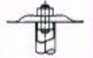 |
Casting Ф16×1 | J1 | ||||
| compression tendon reinforcement | spacing between compression bars |  |
– | J1 | |||
Maximum allowable spacing for transverse reinforcement of rectangular ducts
| Degree of rigidity | The side length of the duct | |||||||
| ≤500 | 630 | 800 | 1000 | 1250 | 1600 | 2000 | ||
| maximum spacing allowed | ||||||||
| low pressure pipeline | G1 | 3,000 | 1600 | 1250 | 625 | Do not use | ||
| G2 | 2000 | 1600 | 1250 | 625 | 500 | 400 | ||
| G3 | 2000 | 1600 | 1250 | 1000 | 800 | 600 | ||
| G4 | 2000 | 1600 | 1250 | 1000 | 800 | 800 | ||
| G5 | 2000 | 1600 | 1250 | 1000 | 800 | 800 | ||
| G6 | 2000 | 1600 | 1250 | 1000 | 800 | 800 | ||
| medium pressure pipeline | G1 | 1250 | 625 | Do not use | ||||
| G2 | 1250 | 1250 | 625 | 500 | 400 | 400 | ||
| G3 | 1600 | 1250 | 1000 | 800 | 625 | 500 | ||
| G4 | 1600 | 1250 | 1000 | 800 | 800 | 625 | ||
| G5 | 1600 | 1250 | 1000 | 800 | 800 | 800 | ||
| G6 | 2000 | 1600 | 1000 | 800 | 800 | 800 | ||
5. Form air duct inlet
① The mechanical air duct is connected by a joint angle former, which strengthens the sealing of the duct.
② The duct closing seam is made by hydraulic seam closing machine, which can effectively ensure the tightness and tightness of the joint connection.
And it greatly improves the beautiful performance of the air duct.
③ The connection between the secondary duct and the main duct is made by sewing joint or pulling the rivet on the opposite side and the main duct is riveted, and the connection is sealed with glass glue to prevent air leakage.
④ The connection between the duct flanges and the flanges is made through special TDC flange corners, which are inserted into the flanges using a corner insertion machine.
6. Air duct seal
①The TDC/TDF duct must be sealed at the flange corners, inside and outside the branch and main connection.
The low pressure duct must be sealed 40-50 mm into the duct at the bend of the duct joint.
The high pressure duct must also be sealed at the longitudinal bite and the composite part of the air duct.
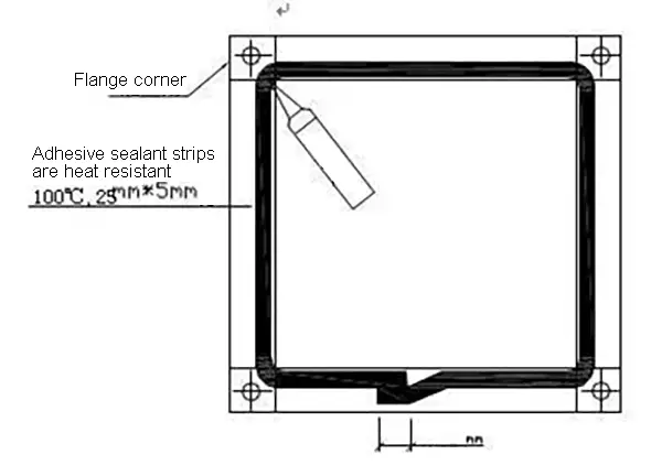
② The four corners of the TDC/TDF duct flange must be sealed with glass glue to prevent leakage.
The joint corner bite should be sealed with glass glue to prevent leakage at the location 30 mm below the flange corner, and the sealant should be located on the positive pressure side of the duct.
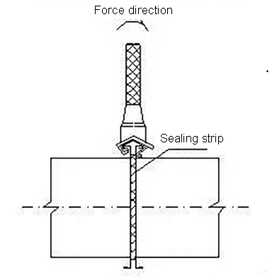
③Flange sealing strips should be installed close to the outside of the flange or in the middle of the flange.
When the flange sealing strip overlaps the end face of the flange, the value should be 30-40 mm.
④The penetration of the pipeline during the process of strengthening, connecting and installing the pipeline, etc. must be sealed with glass sealant.
⑤The tightness of the air duct must meet the requirements in the following table.
Allowed air leakage from rectangular metal duct
|
Pressure (Shovel) |
Allowed air leakage (m³/(h m 2 )) |
| low pressure air duct (P≤500Pa) |
≤0.1056P0.65 |
| medium pressure air duct (500<P≤1500 Pa) |
≤0.0352P0.65 |
| high pressure air duct (P>1500 Pa) |
≤0.0117P0.65 |
V. TDC/TDF Duct Installation
1. Air duct connection
① The semi-finished air duct is processed according to the sketch drawn and numbered according to the system.
The air duct is formed, reinforced and connected according to the construction site number.
②The air duct flanges are coated with a sealing rubber gasket to increase the airtightness of the air duct.
③The four corners of the duct are connected by galvanized screws.
④When the large side size of the air duct exceeds 450mm, to strengthen the strength of the flange and the air duct, a flange fixing plate is required.
⑤The range of the flange fixing clip is in accordance with the following table:
| The side length of the duct (mm) | Flange Clamp Installation Diagram | Flange Clamp Installation Requirements | Flange Clamp Standard Length Size |
| 0→200 | 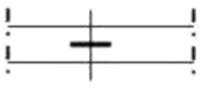 |
no need to add |
120-150mm |
| 250-550 |  |
add one to the center | |
| 600-1000 | 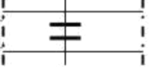 |
add two equidistant | |
| ≥1050 | 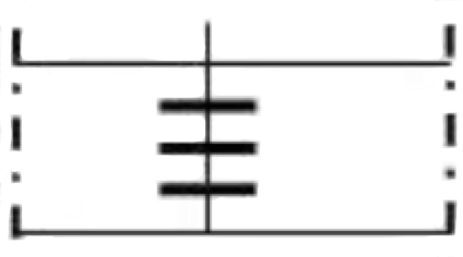 |
add one with spacing below 150 |
2. Introduction to air duct installation
1 ) Air duct assembly
2) Install the flange corner
① Corner insertion

② Corner fixing

③ Apply leak-proof glue and install flange sealant
④ Bolted connection at four corners

⑤ Mount the flange clamp
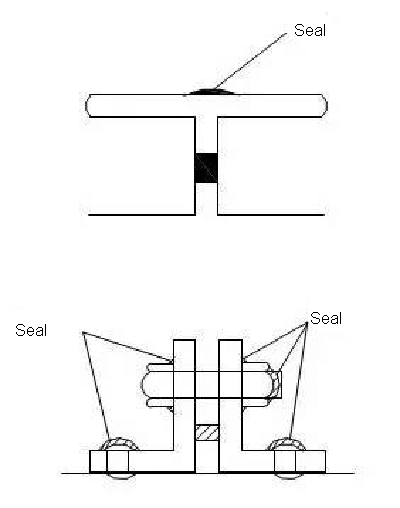
3. TDF/TDC Duct Flange Connection
The four corners of the TDF/TDC flange are connected by galvanized bolts.
There are two types of flange edge connection: flange spring clamp connection and top wire clamp connection.
The installation distance must be less than or equal to 150mm.
Flange spring clamp connection (commonly known as code hook, flange buckle)
The flange spring clamp can be produced by TDF/TDC flange forming machine and its plate thickness is 1mm.
It is suitable for connecting TDC/TDF ducts with air pressure less than or equal to 1500Pa and side length less than or equal to 1350mm.

Flanged Spring Clamp Installation Diagram
U-bolt connection
The U-bolt connector needs to be customized or purchased from the market, and the board thickness is 3mm.
It is suitable for TDF/TDC duct connection with air pressure less than or equal to 1500Pa and side length greater than 1350mm.

U-bolt connection installation diagram
SAW. Conclusion
In summary, it appears that, as a new type of air duct, the TDF/TDC duct produced on a large scale in the factory has significant advantages in the application of ventilation and air conditioning engineering.
Its convenient and efficient construction technology effectively reduces the construction cost of the project, speeds up the construction progress, improves the construction quality, and reduces noise pollution and paint pollution at the construction site.
However, due to insufficient flange strength, traditional angled flange ducts are still required for large-sided air ducts with a long side of more than 2000mm and high-pressure ducts with air pressure greater than 1500Pa.
In practical applications, TDC/TDF duct or angle flange duct should be reasonably selected according to the design characteristics.


