Generally, sheet metal refers to metal materials with uniform thickness. Common sheet metal materials include stainless steel, galvanized steel, tinplate, copper, aluminum and iron. This article mainly reviews the basic principles of sheet metal product design.
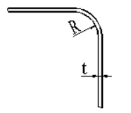
1. Minimum bending radius for sheet metal parts
When bending sheet metal parts, if the corner radius is too small, the outer surface will be prone to cracking. If the corner radius is too large, the precision of the bent part will not be easily maintained due to springback. Therefore, a minimum bending radius is specified, as shown in the table below.
| Material | Minimum bending radius (R) |
| Cold rolled sheet, galvanized sheet, galvanized sheet | R ≥ 2t |
| brass plate | R ≥ 1t |
| Aluminum Alloy Plate | R ≥ 1.2t |
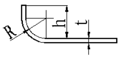
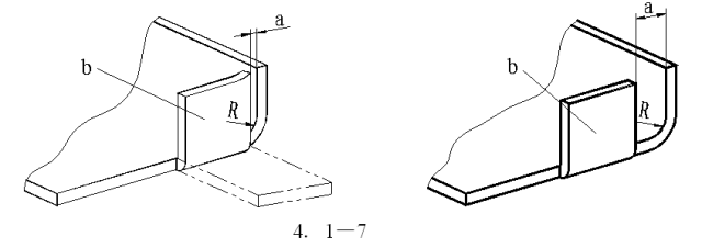
2. The height of the ruler at the fold should not be too small; otherwise, it will be difficult to form sufficient bending moment to obtain precisely shaped parts.
The value of h must not be less than R+2t, as shown below.
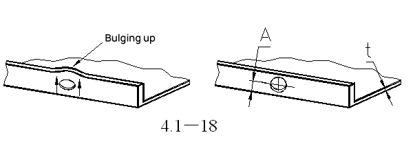
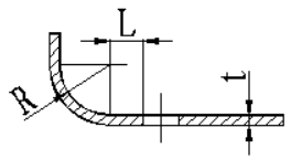
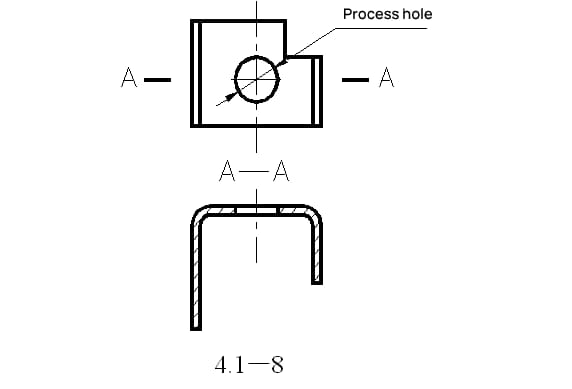
3. When punching near a bent edge, the distance L from the edge of the hole to the center of the bending radius R should not be too small to avoid deformation of the hole after bending.
The value of L must not be less than 2t, as shown in the figure below.
4. When the
5. On U-shaped folded pieces, it is better to have folded edges of equal length to avoid shifting to one side during folding.
Related Reading: V and U Shaped Bending Strength Calculator
If not permitted, a process location orifice can be defined, as illustrated in Figure 4.1-8.
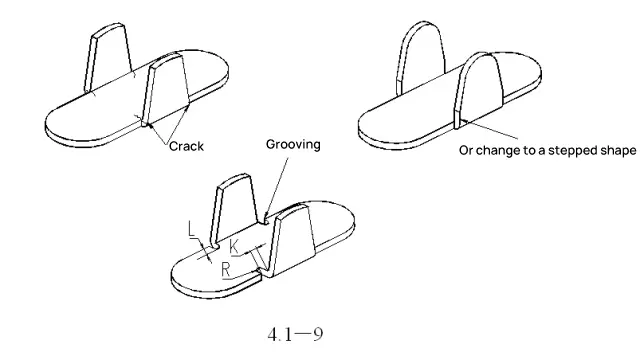
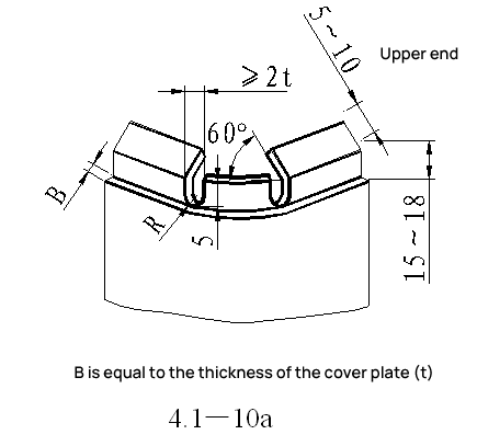
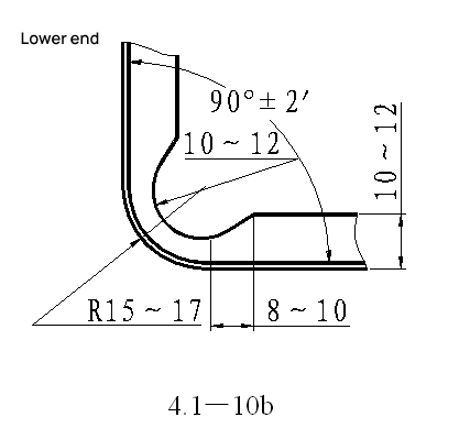
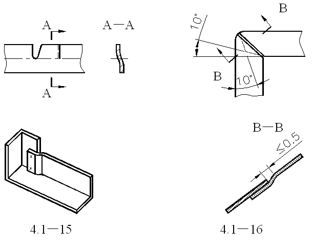
6. To prevent cracking or distortion during lateral (trapezoidal) bending.
Design a reserved slot or change the base to a step shape. The width of the groove K must not be less than 2t and the depth of the groove L must be at least t+R+K/2.
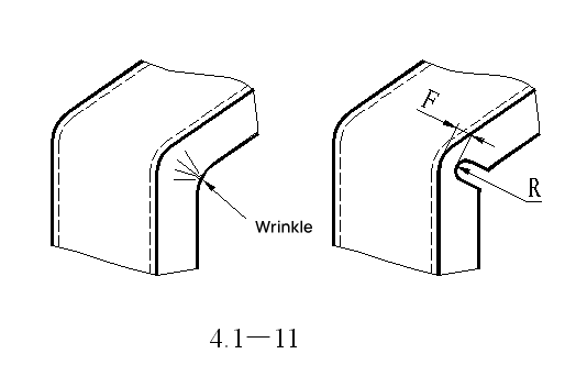
7. To avoid wrinkling due to compression of the material at the corners during bending, design a reserved notch.
For example, the notch design at the corner of the outdoor unit side plate (top and bottom).
8. To avoid wrinkling on the flat sides of a right angle after bending, design a reserved notch.
| R | F |
| 3 | 1.6 |
| 6 | 3 |
| 10 | 4.6 |
| 20 | 8 |
| 30 | 11 |
| 40 | 13 |
| 50 | 15 |
9. To prevent springback after bending, design a notch.
10. To prevent cracking after punching and subsequent bending, design a notch.
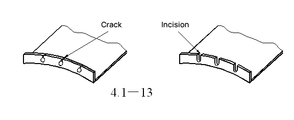
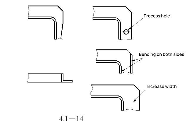
11. To prevent one side from shrinking inwards during bending.
This can be resolved by designing a process location hole, bending both sides simultaneously, or increasing the flange width to resolve shrinkage issues.
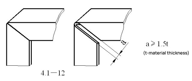
12. Overlapping shape when bending at right angles.
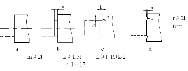
13. Lump Bending
If bent as in Figure a, where the bend line coincides with the step line, cracking and deformation can sometimes occur at the root. Therefore, offset the bend line from the step line as in Figure b, or design a notch as shown in Figures c and d.
14. To avoid deformation of the holes on the bent surface due to stress, the distance from the edge (to the bottom root) should not be less than A≥4.