FIGURE 1 Examples of sheet metal parts.
(a) Stamped parts.
(b) Parts produced by spinning.

TABLE 1 General Characteristics of Sheet Metal Forming Processes (in alphabetical order)
| Training process | Characteristics |
|---|---|
| Design | Shallow or deep parts with relatively simple shapes, high production rates, high tooling and equipment costs |
| Explosive | Large sheets with relatively simple shapes, low tooling costs but high labor costs, low quantity production, long cycle times |
| Incremental | Simple to moderately complex shapes with good surface finish; low production rates, but no need for dedicated tools; limited materials |
| Magnetic pulse | Surface forming, bulging and stamping operations on relatively low-strength sheets require special tools |
| Peen | Surface contours on large sheets, flexibility of operation, generally high equipment costs, process also used to straighten molded parts |
| To roll | Long parts with constant simple or complex cross-sections, good surface finish, high production rates, high tooling costs |
| Rubber | Drawing and embossing of simple or relatively complex shapes, sheet surface protected by rubber membranes, flexibility of operation, low tooling costs |
| Wiring | Small or large axisymmetric parts; good surface finish; low tooling costs, but labor costs can be high unless operations are automated |
| Stamping | It includes a wide variety of operations such as punching, stamping, embossing, bending, flanging and coining; simple or complex shapes formed at high production rates; tool and equipment costs may be high, but labor costs are low |
| To stretch | Large parts with shallow contours, low quantity production, high labor costs, tooling and equipment costs increase with part size |
| Superplastic | Complex shapes, fine details and close dimensional tolerances, long forming times (hence production rates are low), parts not suitable for use at high temperatures |
FIGURE 2
(a) Schematic illustration of punch and die shearing, indicating some process variables.
Characteristic features of
(b) a drilled hole and
(c) the bullet.
(Note that the scales of (b) and (c) are different.)

FIGURE 3
(a) Effect of clearance, c, between punch and die in the shear deformation zone. As the gap increases, the material tends to be pulled into the die rather than being sheared out. In practice, gaps generally vary between 2 and 10% of the sheet thickness.
(b) Microhardness (HV) contours for a hot-rolled AISI 1020 steel 6.4 mm (0.25 in.) thick in the shear region.

FIGURE 4
(a) Perforation (drilling) and suppression.
(b) Examples of various die cutting operations on sheet metal.
Lanceting involves cutting the leaf to form a flap.

FIGURE 5
(a) Comparison of cut edges produced by conventional (left) and thin-cut (right) techniques.
(b) Schematic illustration of a configuration for fine suppression.

FIGURE 6 Cutting with rotating knives.
This process is similar to opening cans.

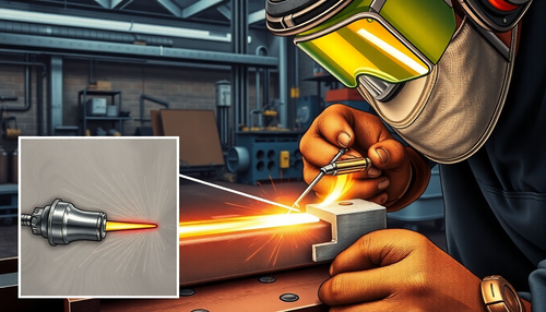
FIGURE 7 An example of blanks welded by Taylor
Production of an external side panel of a car body by laser welding and stamping.

FIGURE 8 Examples of laser-welded and stamped automotive body components.

FIGURE E 9
Schematic illustrations of the shaving process.
(a) Shave a cut edge.
(b) Cutting and shaving combined in a single stroke.

FIGURE 10 Examples of the use of shear angles in punches and dies.

FIGURE E 11 Schematic illustrations
(a) before and (b) after dulling a common washer in a composite die.
Note the separate movements of the die (to stamp) and the punch (to make the hole in the washer).
(c) Schematic illustration of the fabrication of a washer in a progressive die.
(d) Formation of the top of an aerosol spray can into a progressive die.
Note that the part is fixed to the strip until the last operation is completed.

TABLE 2 Important characteristics of metal for sheet metal forming operations
| Feature | Importance |
|---|---|
| Stretching | Determines the ability of sheet metal to stretch without strangulation and failure; high strain hardening exponent (n) and strain rate sensitivity exponent (m) are desirable |
| Yield Point Elongation | Typically seen with mild steel sheets (also called Luder strips or stretcher strains); results in depressions on the surface of the sheet; can be eliminated by temper rolling, but the sheet must be formed within a certain time after rolling |
| Anisotropy (planar) | Shows different behavior in different flat directions, present in cold-rolled sheets due to preferential orientation or mechanical fiber, causes ears in deep drawing, can be reduced or eliminated by annealing, but with reduced strength |
| Anisotropy (normal) | Determines the thinning behavior of metal sheets during stretching, important in deep drawing |
| grain size | Determines the surface roughness of stretched sheets; the coarser the grain, the rougher the appearance (like an orange peel); also affects the strength and ductility of the material |
| Residual stresses | Typically caused by non-uniform deformation during forming, results in distortion of the part when sectioned, can lead to stress corrosion cracking, reduced or eliminated by stress relief |
| spring back | Due to the elastic recovery of the plastically deformed sheet after unloading, it causes distortion of the part and loss of dimensional accuracy, which can be controlled by techniques such as excessive bending and punch seating. |
| Wrinkling | Caused by compression stresses in the plane of the sheet; may be questionable; depending on its extension, it can be useful to give rigidity to the parts, increasing their section modulus; can be controlled by suitable tool and die design |
| Quality of cut edges | It depends on the process used; the edges may be rough, not square, and contain cracks, residual stresses and a hardened layer, which are detrimental to the formability of the sheet; Edge quality can be improved through fine cutting, clearance reduction, scraping, and improvements in tool and die design and lubrication |
| Leaf surface condition | It depends on the sheet lamination practice; important in the formation of sheets, as it can cause tears and poor surface quality |
FIGURE 12
(a) Elongation of the yield point in a sheet metal sample.
(b) Lüder bands on low carbon steel sheet.
(c) Stretching deformations at the bottom of a steel can for household products.

FIGURE 13
(a) A cupping test (Erichsen test) to determine the formability of sheet metal.
(b) Results of bulge tests on steel sheets of various widths. The leftmost sample is basically subjected to simple tension. The rightmost sample is subjected to equal biaxial stretching.

FIGURE 14
(a) Deformations in deformed circular grid patterns.
(b) Forming limit diagrams (FLD) for various sheet metals. Although the major strain is always positive (elongation), the minor strain can be positive or negative. R is the normal anisotropy of the sheet, as described in Section 4.

FIGURE E 15
The deformation of the grid pattern and the tearing of the sheet metal during forming. The major and minor axes of the circles are used to determine the coordinates on the formation boundary diagram in Fig. 14b.

FIGURE 16
Inflection terminology. Note that the bend radius is measured to the inside surface of the bent part.

FIGURE 17
(a) and (b) The effect of elongated inclusions (stringers) on cracking as a function of the bending direction in relation to the sheet's original rolling direction.
(c) Cracks on the outer surface of an aluminum strip bent at a 90° angle. Also note the narrowing of the upper surface in the area of curvature (due to the Poisson effect).

TABLE 3 Minimum bending radius for various metals at room temperature
| Material | Illness | |
| Soft | Hard | |
| aluminum alloys | 0 | 6T |
| Beryllium copper | 0 | 4T |
| Brass (low lead) | 0 | 2T |
| Magnesium | 5T | 13T |
| Austenitic stainless steel | 0.5T | 6T |
| Low carbon, low alloy and HSLA | 0.5T | 4T |
| Titanium | 0.7T | 3T |
| Titanium alloys | 2.6T | 4T |
FIGURE 18
Relationship between R/T and area traction reduction for sheet metal. Note that sheet metal with a tensile area reduction of 50% can be folded in on itself in a process like folding a piece of paper without cracking.

FIGURE E 19
Springback in flexion. The part tends to recover elastically after bending and its radius of curvature becomes larger. Under certain conditions, it is possible for the final bend angle to be smaller than the original angle (negative springback).

FIGURE 20 Methods for reducing or eliminating springback in bending operations.

FIGURE 21
Common bending operations showing the die opening dimension, C , used in calculating bending forces.

FIGURE E 22 Examples of various bending operations.

FIGURE 23 (a) to (e) Schematic illustrations of various bending operations on a press brake. (f) Schematic illustration of a press brake.

FIGURE 24 (a) Formation of accounts with a single matrix. (b) to (d) Bead formation with two dies in a press brake.

FIGURE E 25 Various flanging operations.
(a) Flat plate flanges.
(b) Ripples.
(c) Punching sheet metal to form a flange. In this operation, a hole does not need to be pre-drilled before the punch descends. Note, however, the ridges along the circumference of the flange.
(d) The flanging of a pipe.
Note the thinning of the flange edges.

FIGURE E 26
(a) Schematic illustration of the logging process.
(b) Examples of profiled cross sections.

FIGURE 27 Pipe bending methods.
Internal mandrels or filling tubes with particulate materials such as sand are often necessary to prevent tubes from collapsing during bending.
Tubes can also be bent by a technique in which a rigid helical tension spring is placed over the tube. The gap between the outer diameter of the tube and the inner diameter of the spring is small; thus, the tube cannot bend and the curvature is uniform.

FIGURE 28
(a) The bulging of a tubular part with a flexible plug. Water jugs can be made by this method.
(b) Production of plumbing fittings by expanding tubular parts under internal pressure. The bottom of the piece is then drilled to produce a “T”.

FIGURE 29 Schematic illustration of a stretch forming process. Aircraft aluminum skins can be made by this method.

FIGURE 30 The metal forming processes involved in manufacturing a two-piece aluminum beverage can.

FIGURE E 31
(a) Schematic illustration of the deep drawing process on a circular sheet metal part. The removal ring facilitates removal of the formed cup from the punch.
(b) Process variables in deep drawing. Except for punch force, F all parameters indicated in the figure are independent variables.

FIGURE E 32
Deformations in a tensile test specimen removed from a sheet metal part. These deformations are used in determining the normal and planar anisotropy of the sheet metal.

TABLE 4 Typical ranges of average normal anisotropy, average R for various sheet metals
| Zinc alloys | 0.4-0.6 |
|---|---|
| Hot rolled steel | 0.8-1.0 |
| Cold rolled steel with edges | 1.0-1.4 |
| Cold rolled steel and tempered with aluminum | 1.4-1.8 |
| aluminum alloys | 0.6-0.8 |
| Copper and brass | 0.6-0.9 |
| Titanium alloys (α) | 3.0-5.0 |
| Stainless steels | 0.9-1.2 |
| High-strength, low-alloy steels | 0.9-1.2 |
FIGURE 33
The relationship between the average normal anisotropy and the limiting stretch rate for various sheet metals.
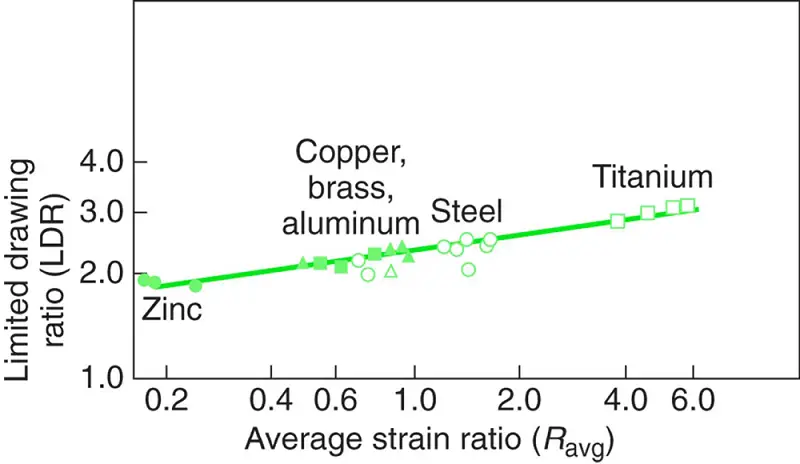
FIGURE E 34
Earring made of drawn steel cup, caused by the planar anisotropy of the sheet.

FIGURE 35
(a) Schematic illustration of a drawing string.
(b) Metal flow during the design of a box-shaped part while using spheres to control the movement of the material.
(c) Deformation of circular grids on the flange in deep drawing.

FIGURE E 36
A write operation with two arrays. Letters, numbers and designs on sheet metal parts can be produced by this process.

FIGURE E 37
(a) Aluminum beverage cans. Note the excellent surface finish.
(b) Detail of the can lid, showing the integral rivet and marked edges for the pop-top.

FIGURE 38
Examples of bending and stamping sheet metal with a metal punch and with a flexible pad serving as a female die.

FIGURE 39
The process of hydroforming (or fluid formation). Note that, in contrast to the common deep drawing process, the pressure in the dome forces the walls of the cup against the punch. The cup comes with the punch; in this way, the deep drawing capacity is improved.

FIGURE 40
(a) Schematic illustration of the tube hydroforming process.
(b) Example of hydroformed tube parts. Automotive structural and exhaust components, bicycle frames, and hydraulic and pneumatic accessories are produced using tube hydroforming.

FIGURE E 41
Hydroformed automotive radiator closure.

FIGURE 42
Sequence of operations in the production of a hydroformed tubular component:
(1) pipe cut to length;
(2) after flexion;
(3) after hydroforming.

FIGURE 43
Schematic illustration of expanding a tube to a desired cross section through (a) conventional hydroforming and (b) pressure sequence hydroforming.

FIGURE E 44
View of the tube hydroforming press, with the bent tube placed in the forming die.

FIGURE 45
(a) Schematic illustration of the conventional spinning process.
(b) Types of conventionally spun parts. All parts are axisymmetric.

FIGURE E 4 6
(a) Schematic illustration of the shearing process for manufacturing conical parts. The chuck can be shaped so that curvilinear parts can be turned. (b) and (c) Schematic illustrations of the tube spinning process.

FIGURE 47
(a) Illustration of an incremental forming operation. Note that no chuck is used and that the final shape of the part depends on the path of the rotating tool.
(b) An automotive headlight reflector produced by CNC incremental forming. Note that the part does not need to be axisymmetric.

FIGURE 48
Types of structures made by superplastic forming and diffusion bonding of metal sheets. Such structures have a high stiffness-to-weight ratio.

FIGURE 49
(a) Schematic illustration of the explosive formation process.
(b) Illustration of the confined method of explosive pipe bulging.

FIGURE 50
(a) Schematic illustration of the magnetic pulse formation process used to form a tube over a plug.
(b) Aluminum tube collapsed over a hexagonal plug by the magnetic pulse formation process.

FIGURE 51
(a) A selection of common dishes.
(b) Detailed view of different surface textures and plate finishes.

FIGURE E 52
Manufacturing sequence for plate production.

FIGURE 53
Hammering dishes.
(a) Automated hammering on a hammering machine;
(b) manual hammering of cymbals.

FIGURE 54
Methods for manufacturing honeycomb structures:
(a) expansion process;
(b) curling process;
(c) assembling a honeycomb structure into a laminate.

FIGURE E 55
Efficient grouping of parts for optimal use of material in blanking.

FIGURE 56
Control of tearing and buckling of a flange in right angle curvature.

FIGURE E 57
Application of notches to avoid tears and wrinkles in right angle bending operations.

FIGURE E 58
Stress concentrations near curves.
(a) Use of a crescent or ear for a hole near a curve.
(b) Reducing the severity of the tab on the flange.

FIGURE E 59
Applying (a) scoring or (b) embossing to obtain a sharp inner radius at the fold. Unless properly designed, these features can lead to fracture.

FIGURE 60
(a) to (f) Schematic illustrations of types of press structures for sheet metal forming operations. Each type has its own characteristics of rigidity, capacity and accessibility.
(g) A large stamping press.

FIGURE 61
Cost comparison for manufacturing a round sheet metal container by conventional spinning or deep drawing.
Note that for small quantities, spinning is more economical.

PS: we have just prepared for you the PDF version of the sheet metal forming process, you can download it here.