1. Preamble
42CrMo is a high-strength steel alloy known for its excellent mechanical properties, such as high strength and toughness, good hardenability and lack of brittleness due to tempering.
After quenching and tempering, it has a high fatigue limit, impact resistance and good impact toughness at low temperatures, making it ideal for manufacturing large and medium-sized steel components that require strength and toughness.
Our company chose 42CrMo steel to manufacture a large pivot, and the manufacturing process involves the following steps: blank forging, normalizing, rough machining, quenching and tempering, finishing, induction hardening circle and grinding circle.
The pivot structure is illustrated in Figure 1.
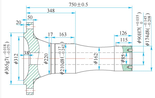
Fig. 1 Pivoting Structure
2. Defective parts overview
Cracks may occur on the pivot shaft during quenching, tempering and quenching processes.
The crack usually appears in the transition arc area between the pivot shaft root and the flange.
The entire pivot shaft breaks along the radial direction and extends to the big end flange.
The pivot shaft may crack completely. See Fig. 2 for the shape and location of the crack.
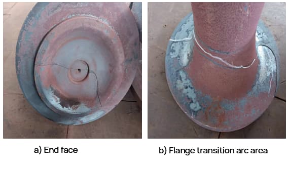
Fig. 2 Crack morphology after quenching, tempering and quenching
The quenching and tempering process of this part involves keeping it at 840℃ for 3 hours, followed by oil cooling quenching once it is removed from the furnace. The quenching time is 30 minutes and Houghton K oil is used as the quenching oil.
Several batches of this product have been produced without cracking.
To analyze the causes of cracks, a cracked part was sampled from the large end flange and its chemical composition, metallographic structure and cracks were analyzed. Samples were taken from the flange crack (see Fig. 3) for analysis.
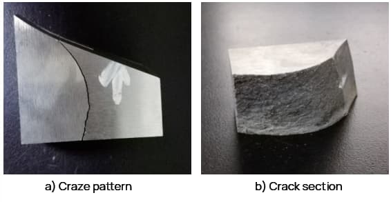
Fig. 3 Flange sampling
See Table 1 for chemical composition analysis results
Table 1 Chemical Composition (Mass Fraction) of the 42CrMo Steel Pivot (%)
| Element | Standard value | Measured value |
| W | 0.38~0.45 | 0.43 |
| Yes | 0.17~0.37 | 0.28 |
| Mn | 0.5~0.8 | 0.68 |
| s | ≤0.035 | 0.007 |
| P | ≤0.035 | 0.016 |
| Cr | 0.9~1.2 | 1 |
| Mo | 0.15~0.25 | 0.2 |
| No | ≤0.30 | 0.034 |
| Ass | ≤0.30 | 0.046 |
| Al | – | 0.026 |
The metallographic structure is shown in Fig.
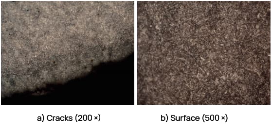
Fig. 4 Metallographic Crack and Surface Structure
The analysis results indicate that the chemical composition of 42CrMo steel meets the technical requirements. The measured surface hardness is 296HBW, which is within the required range of 277-331HBW. The metallographic structure is tempered sorbite, and the central structure is tempered sorbite+ferrite.
The crack on the part is arc-shaped and there is no decarburization on either side of the crack, indicating that there was no crack before quenching and tempering, and no other abnormalities were observed.
Physical and chemical analysts attribute the crack to excessive stress during quenching, tempering, and quenching, based on the sample.
However, due to the size of the part and the challenge of sampling, the author suggests that the sample cutting position may be the crack growth area and not the crack initiation location, requiring further analysis.
As the crack source cannot be identified through the fracture surface, it is proposed to cut the part to locate the crack source. Flame or plasma cutting may impact the fracture site, therefore, wire cutting is recommended to cut the crack site in the axis transition zone of the defective part.
When the cut reaches 1/3 of the diameter, the pivot axis divides into two sections, enabling a more in-depth analysis of the cause of the crack.
3. Analysis of the causes of crack
The fracture morphology after wire cutting is shown in Fig.
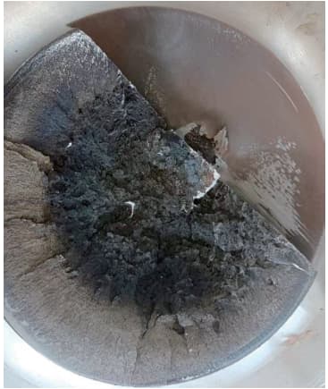
Fig. 5 Position of the fracture after cutting the wire
The center of the fracture appears brown, while the outside has a normal metallic color. The brown color in the center is abnormal and probably caused by oxidation.
Analysis indicates that cracks likely existed in the center of the part prior to quenching, tempering and subsequent forging, normalizing and quenching processes. The cracks would have undergone oxidation during these processes, leading to brown discoloration.
To confirm this hypothesis, a sample was taken from the brown area and analyzed. The sample was cut from the center in the axial direction. After cutting and processing, it was found that numerous cracks were distributed radially, as illustrated in Figure 6.
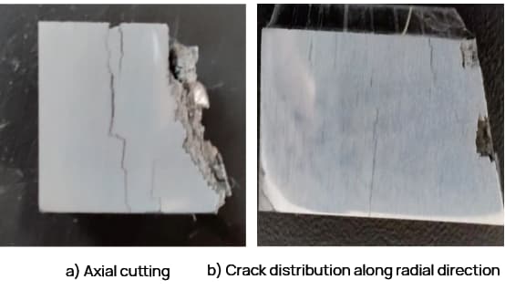
Fig. 6 Fissure Fracture Location
Sample analysis shows that the sample has an obvious banded structure (Grade 4), as shown in Fig.
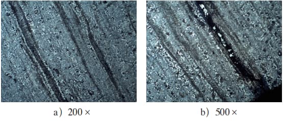
Fig. 7 Metallographic Structure of the Crack Center
The cracks, which are multiple and approximately parallel, are distributed along the direction of the banded structure and perpendicular to the direction of forging.
The author believes that there were cracks present before the quenching and tempering process of the pivot shaft, and these cracks were centrally located, with no cracks visible on the surface.
During the quenching and tempering process, the cracks expanded due to the influence of organizational and thermal stress, with the banded structure also playing an important role.
As a result, it is necessary to carry out further analysis to determine whether there were problems such as insufficient forging temperature and unreasonable forging rate during the forging process.
To prevent defective parts from entering the market, products in process were thoroughly investigated.
All in-process products have undergone NDT testing using an ultrasonic flaw detector.
After investigation, two abnormal products were discovered and their production serial numbers were verified.
It turned out that the production serial numbers of the two abnormal products were part of the same batch of forgings that contained the cracked parts.
To validate the initial analysis and judgment, wire cutting was performed on the abnormal pieces found along the axial direction.
The cut surface clearly revealed the presence of several detailed cracks, perpendicular to the forging direction, as illustrated in Fig.
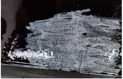
Fig. 8 Cutting surface of defective parts
Through additional checks, it was concluded that the crack was generated during forging.
4. Conclusion
1)The fracture of the pivot axis can be directly attributed to the forging crack formed during the forging process of the part. This crack expanded during quenching and tempering, and the presence of a banded structure also contributed to its growth.
2)When performing failure analysis, it is important to carefully locate the source of the crack. Different sampling locations can significantly impact analysis results. Therefore, it is essential to analyze and identify the cause from the source to avoid deviations.
3) Strengthening incoming inspection of raw materials is crucial to prevent defective parts from entering the production process.