Welding position refers to the relative positioning of the workpiece on the welding equipment during the welding operation. There are four basic types of welding positions: flat, horizontal, vertical and overhead. Each welding position has specific operational requirements and precautions.
Flat position: This is the most common welding position, suitable for most welding scenarios. Welding performed in this position is called flat welding.
Horizontal position: This position is typically used when the weld seam needs to be observed or handled from the side. In horizontal welding, the selection of electrode angle and current is particularly important to ensure the quality of the weld seam.
Vertical position: Vertical welding involves placing the workpiece in a vertical position for welding. This position is suitable for welding long, linear materials such as pipes. In vertical welding, electrode selection and adjustment of welding parameters are crucial to ensure welding quality.
Overhead position: Overhead welding is a position where welding is done from below the weld seam, making it a challenging position as the operator needs to align the weld seam from above. During overhead welding, the welding current should be 10% – 15% lower than during flat welding, and short arc operation should be used.
When choosing a welding position, factors such as welding thickness, number of welding layers and joint type need to be considered. For example, when soldering high-power transistors, special attention may be required to ensure proper insertion of the conductor position, and soldering time should be minimized for better heat dissipation.

Types of welding position
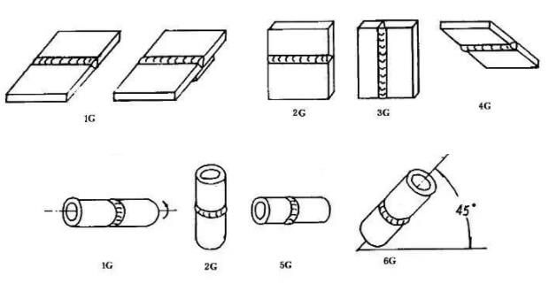
The positions of slot welds are classified as 1G, 2G, 3G, 4G, 5G and 6G, respectively representing flat welding, horizontal welding, vertical welding, suspended welding, horizontal fixed welding of pipelines and 45° inclined fixed welding of pipelines.
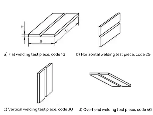
Plate butt welding:
- (1) Flat position, denoted as 1G;
- (2) Horizontal position, denoted as 2G;
- (3) Vertical position, denoted as 3G;
- (4) Aerial position, denoted as 4G.
Pipe Butt Welding:
- (1) Horizontal rotation, denoted as 1G;
- (2) Vertical fixed position, denoted as 2G;
- (3) Horizontal fixed position, denoted as 5G, 5GX;
- (4) 45 degree fixed position, indicated as 6G, 6GX.
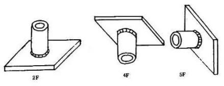
Butt joint welding between tube and plate:
- (1) Horizontal rotation, denoted as 2FRC;
- (2) Vertical fixed position, flat welding, called 2FG;
- (3) Vertical fixed position, suspended welding, indicated as 4FG;
- (4) Horizontal fixed position, designated as 5FG;
- (5) Fixed 45 degree position, denoted as 6FG.
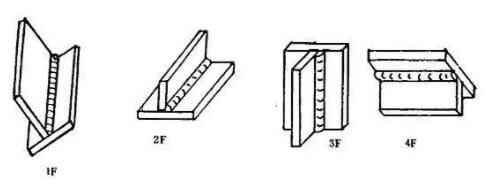
Plate fillet welding:
Plate fillet welds are classified as 1F, 2F, 3F, and 4F, representing ship-type welding, horizontal welding, vertical welding, and overhead welding, respectively.
Pipe plate or fillet welds are classified as 1F, 2F, 2FR, 4F, and 5F, representing 45-degree rotary welding, transverse welding (with the tube axis vertical), tube axis horizontal rotary welding, and horizontal overhead welding fixed to the tube axis, respectively.
Pin welding:
- (1) Flat position, denoted as 1S;
- (2) Horizontal position, denoted as 2S;
- (3) Aerial position, denoted as 4S.
- According to AWS, the flat position is denoted as F, the horizontal position is denoted as H, the vertical position is denoted as V, and the overhead position is denoted as OH.
1g, 2g, 3g, 4g, 5g, 6g Welding position explained
1. Flat welding (1G)
1 G is flat welding
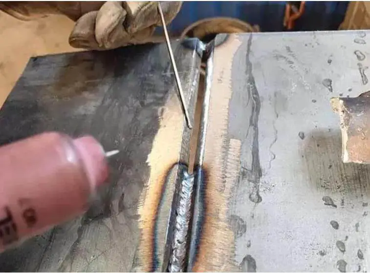
1G welding features:
Metal fusion welding mainly relies on its own weight to flow into the weld pool.
The shape and composition of the molten pool are simple to maintain and control.
When welding metal with the same plate thickness, the welding current required for flat welding is higher compared to other welding positions, leading to higher production efficiency.
However, slag and molten pool are prone to mixing, particularly when welding flat fillet welds, causing slag to advance easily and form slag inclusions.
Acidic electrodes can make it difficult to distinguish between slag and molten pool, while alkaline electrodes provide clarity.
Incorrect welding parameters and techniques can result in defects such as bead formation, undercutting and welding deformation.
When welding on one side, if the back is free-forming, the first weld may present problems such as uneven penetration or poor formation of the back.
Key points of 1G welding:
According to the thickness of the plate, a welding rod with a larger diameter and higher welding current can be selected.
When welding, the electrode and welding must form an angle of 60-80°, and the separation of slag and liquid metal must be controlled to prevent the formation of slag.
For plate thicknesses ≤6mm, a Type I groove should generally be used for flat butt welding, and a 3.2-4mm diameter electrode with a short arc welding technique should be used for face, penetration welding. reaching 2/3 of the plate thickness.
Before further sealing, the root cannot be cleaned except in important structures, but the slag must be cleaned and the current can be greater.
If there is confusion between the slag and the molten pool metal in flat butt welding, extend the arc, tilt the electrode forward, and push the slag behind the molten pool to prevent slag inclusion.
For horizontal and inclined welding, upward welding must be used to avoid the inclusion of slag and prevent the weld pool from advancing.
When multi-layer and multi-pass welding is used, consider the number of welding passes and the welding sequence, with each layer not exceeding 4-5 mm.
For T joints, fillets and overlapping flat angle welded joints, if the thickness of the two plates is different, the electrode angle should be adjusted to direct the arc to one side of the thicker plate to ensure uniform heating of the two plates.
Correct selection of strip transport method
(1) For welding thickness less than or equal to 6mm, I-slot flat butt welding is used.
Bilateral welding should employ linear transport of strips to the face weld, at a slightly slow pace.
Back welding should also use linear strip transport, with slightly higher welding current and faster speed.
(2) For sheet thicknesses less than or equal to 6 mm, multilayer welding or multilayer multipass welding can be used when other groove shapes are used.
The first layer of backing welding should use low current electrode, standard low current and linear or serrated electrode welding.
When welding the filler layer, electrodes with larger diameter and short arc welding with higher welding current can be selected.
(3) For T-joint flat fillet welding with leg size less than 6mm, single-layer welding can be chosen, and linear conveying, oblique ring or sawtooth strip methods can be used.
For larger welding leg sizes, multilayer welding or multipass multilayer welding should be used.
The linear strip conveying method is employed for backing welding, and the inclined sawtooth or inclined ring strip conveying can be chosen for the filler layer.
(4) Multi-layer and multi-pass welding should generally use the linear strip welding method.
2. Horizontal welding (2G)
2G is horizontal welding
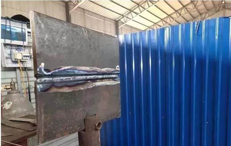
2G welding features:
The molten metal can easily fall into the groove due to its own weight, leading to undercut defects on the upper side and torn weld beads or incomplete penetration defects on the lower side.
Separating molten metal and slag is relatively easy, similar to vertical welding.
Key points of 2G welding:
Type V or type K groove is generally used for horizontal butt welding, and for butt joints with plate thickness of 3 to 4 mm, both sides can be welded using type I groove.
A small diameter electrode should be selected and the welding current should be lower than that used for flat welding. Short arc operation can better control the flow of molten metal.
For welding thick plates, multilayer and multipass welding must be adopted, in addition to support welds.
When using multilayer and multipass welding, special attention must be paid to controlling the overlap distance between welding passes. Each overlap weld must begin 1/3 of the previous weld to avoid irregularities.
The appropriate electrode angle should be maintained according to the specific situation, and the welding speed should be slightly blocked and uniform.
The correct strip transport method must be used:
(1) For type I horizontal butt welding, face welding is best performed using the alternative linear strip conveying method.
For thicker pieces, you must use a linear or small inclined annular strip and a linear strip on the back. The welding current can be increased accordingly.
(2) For other horizontal slot butt welding, if the gap is small, straight strip transportation can be used for butt welding.
If the gap is large, the supporting layer should use reciprocating linear strip conveying, and other layers may use inclined ring strip conveying during multilayer welding. Linear strip conveying should be used during multi-layer, multi-pass welding.
3. Vertical welding (3G)
3G is vertical welding
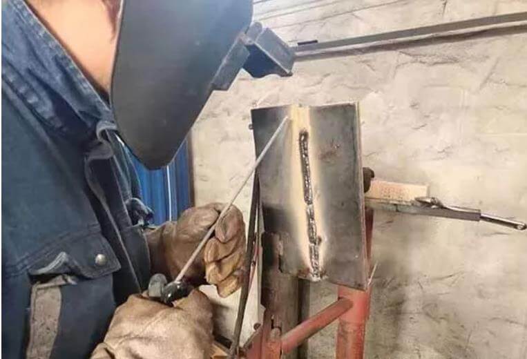
3G welding features:
Molten metal and slag separate easily due to gravity, which can result in defects such as weld beads, undercuts and slag inclusion.
The high temperature of the molten pool causes the metal to flow downward, leading to uneven welding.
Incomplete penetration can occur at the root of T-joint welds and it is easier to control the degree of penetration.
However, welding productivity is lower compared to flat welding.
Key points of 3G welding:
Maintain the correct electrode angle;
Vertical upward welding is commonly used in production, and a specialized welding rod must be used for vertical downward welding to ensure quality.
The welding current for vertical upward welding is 10 to 15% lower than that for flat welding, and a smaller electrode diameter (less than 4 mm) should be selected.
Short arc welding is used to reduce the distance between the droplet transfer and the weld pool.
Adopt the correct method of transporting the strips.
(1) When welding vertically upward in a T-slot butt joint (commonly used for thin plates), linear, serrated and crescent strip conveying methods are commonly used. The maximum arc length should not exceed 6 mm.
(2) For other forms of vertical groove butt welding, the first layer of welding generally employs broken welding, crescent welding with a small overhang, and triangular strip welding. Subsequent layers can be conveyed in a crescent or sawtooth shape.
(3) During vertical welding of T-joints, the electrode must have an appropriate residence time on both sides and upper corners of the weld, and the oscillation amplitude of the electrode must not be greater than the width of the weld. The electrode transport operation is similar to vertical welding of other groove shapes.
(4) When welding the cover layer, the shape of the welding surface will depend on the strip transportation method. A crescent-shaped strip can be used if slightly higher surface quality is required, while a sawtooth strip conveying method can be used for a flat surface (the medium concave shape is related to dwell time).
4. Aerial welding (4G)
4G is aerial welding
4G welding features:
Molten metal falls due to gravity, and controlling the shape and size of the molten pool is challenging.
Strip transportation is difficult and a flat welding surface is not easily achieved.
Defects such as slag inclusion, incomplete penetration, weld bead and poor weld formation are commonly seen. Spatter and diffusion of molten weld metal can cause burn accidents.
Overhead welding is less efficient compared to other welding positions.
Key points of 4G welding:
For overhead butt welding, when the welding thickness is ≤ 4 mm, type I groove should be used, a 3.2 mm electrode should be selected, and the welding current should be moderate.
When the weld thickness is ≥ 5 mm, multi-layer and multi-pass welding should be used.
For overhead welding of T-joint welds, single-layer welding should be used when the weld leg is less than 8 mm, and multi-layer and multi-pass welding should be used when the weld leg is greater than 8 mm.
The correct strip transportation method should be selected based on the specific situation:
(1) When the size of the welding leg is small, linear or linear alternative strip transportation should be used, and single-layer welding should be completed.
When the size of the welding leg is large, multi-layer welding or multi-layer and multi-pass welding strip transportation can be used.
The first layer should be transported using linear strip conveying, and subsequent layers can use inclined triangular strip or inclined ring conveying.
(2) Regardless of the strip transportation method used, the amount of weld metal added to the molten pool at one time should not be excessive.
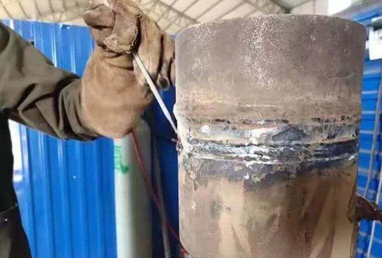
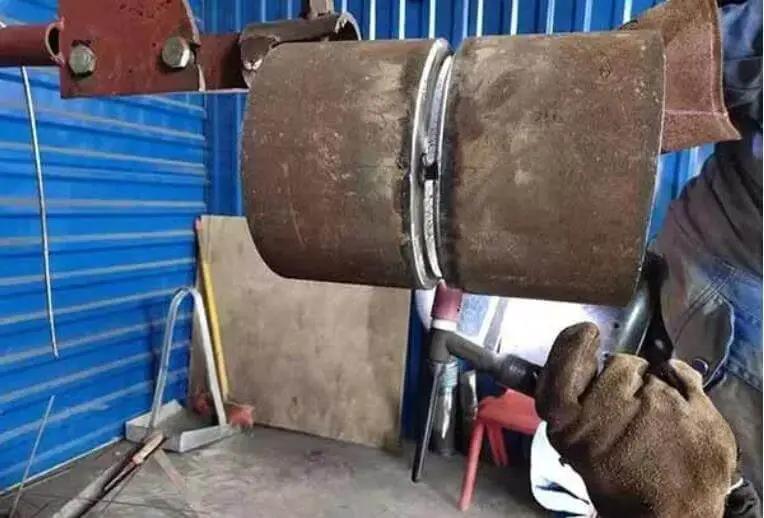
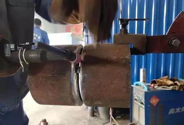
5. Horizontal gas pipeline fixing port (5G)
The horizontal fixing port of the pipeline is 5g position
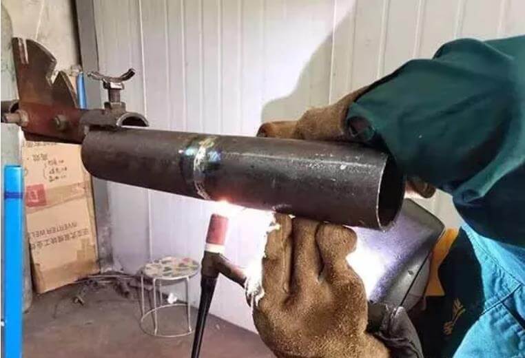
6. Pipe 45° oblique welded joint (6G)
The 45° oblique welded joint of the tube is 6G position
What is the specific impact of welding position selection on welding quality?
The selection of the welding position has a significant impact on the welding quality. First, the welding position directly affects the welding stress and deformation. If the welding position is chosen incorrectly, it may cause excessive deformation or internal stress in the welding. This not only reduces the quality of the welding, but can even result in the welding being dismantled in severe cases.
Additionally, different welding positions can affect the shape and location of the weld pool, especially when welding in vertical, horizontal or overhead positions. Due to the effect of gravity, problems such as undercutting can easily occur.
Therefore, reasonably arranging the position and number of welds is one of the crucial measures to control welding deformation and improve welding quality.
The impact of welding position selection on welding quality is mainly reflected in the following aspects:
- Firstly, it can cause excessive deformation or internal stress in the weldment, affecting its overall performance.
- Secondly, it affects the shape and position of the weld pool, subsequently affecting the quality and aesthetics of the weld.
- Thirdly, by reasonably arranging the position and number of welds, the welding deformation can be controlled effectively, thereby improving the welding quality.
Therefore, during welding operations, the appropriate welding position must be selected based on specific welding requirements, material characteristics and structural rigidity, among other factors, to achieve the best welding results.
What are the pros and cons of vertical and overhead welding in practical applications?
The advantages and disadvantages of vertical and suspended welding in practical applications are as follows:
The strengths of vertical welding lie mainly in material conservation, weight reduction, equipment simplicity, operational flexibility and low cost. It is particularly effective for irregular welds, short welds, overhead welds, welds at high altitudes and in tight spaces, offering flexible application and effortless operation. Welding quality is high due to high arc temperature, faster welding speed and smaller heat affected zone. The equilateral triangle execution method is suitable for vertical welding of chamfered butt joints and T-joints, capable of producing thicker weld cross-sections at one time. Minimizes defects such as slag inclusion, thus increasing production efficiency.
The disadvantage of vertical welding includes the fact that low current voltages are hardly used during top-down welding during operation, resulting in low resistance. Although the formation is aesthetically pleasing, it is essential to maintain the correct electrode angle.
The advantages of aerial welding include good process performance, easy arc initiation, stable arc, less spatter, good slag removal, aesthetically pleasing weld formation, easy mastery of the welding technique, and good resistance to acidic electrode porosity, with the Weld metal rarely causing problems.
The disadvantages of aerial welding are more evident, mainly due to the tendency of the molten metal to fall under the action of gravity, making the transition of the drops and the formation of the weld difficult. In addition, the process performance of solid welding wire is worse, making formation more challenging, and the absence of flux can also affect weld formation.
Vertical welding has clear advantages in terms of operational flexibility, economy and adaptability to complex welds, but may face problems of insufficient strength in some cases. Although overhead welding has its merits in terms of aesthetically pleasing weld formation and technical mastery, its main disadvantage is the increased difficulty of welding due to falling molten metal.
Welding methods and their codes
Each welding method can be carried out using manual welding, mechanized welding or automatic welding, with their codes as shown in the table below.
| Welding method | Code |
| Electromagnetic welding | SMAW |
| Gas Welding | OFW |
| Tig Welding | GTAW |
| Plasma arc welding | GMAW |
| Submerged Arc Welding | MOUNTAIN RANGE |
| Electroslag welding | ESW |
| Plasma arc welding | PAW |
| Gas tungsten arc welding in vertical position | EGW |
| Friction welding | AFR |
| Captive Arc Welding | ONLY |
Test piece forms, positions and their codes
The shapes, positions and their codes of the test pieces are presented in the table below. The position of the test piece basically determines the welding position.
Table 1. Test piece forms, positions and codes.
| Test piece form | Test piece position | Code | |
| Test Piece for Sheet Metal Butt Welding | Flat Welding Test Piece | 1G | |
| Horizontal Welding Test Piece | 2G | ||
| Vertical Welding Test Piece | 3G | ||
| Aerial Welding Test Piece | 4G | ||
| Test piece for tube butt welding | Horizontal Rotation Welding Test Piece | 1G (Rotation) |
|
| Vertical Fixed Welding Test Piece | 2G | ||
| Horizontal Fixed Welding Test Piece | Up welding | 5G | |
| Downward welding | 5GX (down) | ||
| 45° Fixed Welding Test Piece | Up welding | 6G | |
| Downward welding | 6GX (down) | ||
| Tube-Plate Corner Joint Test Piece | Horizontal Rotation Welding Test Piece | 2FRG | |
| Vertical Fixed Flat Welding Test Piece | 2FG | ||
| Vertical Fixed Aerial Welding Test Piece | 4FG | ||
| Horizontal Fixed Welding Test Piece | 5FG | ||
| 45° Fixed Welding Test Piece | 6FG | ||
| Sheet Metal Corner Welding Test Piece | Flat Welding Test Piece | 1F | |
| Horizontal Welding Test Piece | 2F | ||
| Vertical Welding Test Piece | 3F | ||
| Aerial Welding Test Piece | 4F | ||
| Pipe Corner Welding Test Piece (including tube-to-plate corner welding test piece and tube-to-tube corner welding test piece). |
45° Rotation Welding Test Piece | 1F (Rotation) |
|
| Vertical Fixed Horizontal Welding Test Piece | 2F | ||
| Horizontal Rotation Welding Test Piece | 2FR | ||
| Vertical Fixed Aerial Welding Test Piece | 4F | ||
| Horizontal Fixed Welding Test Piece | 5F | ||
| Threaded Stud Welding Test Piece | Flat Welding Test Piece | 1S | |
| Horizontal Welding Test Piece | 2S | ||
| Aerial Welding Test Piece | 4S | ||
Test pieces with and without supports
Sheet metal butt welding test piece, tube butt welding test piece and tube-plate corner joint test piece can be divided into two types: with and without backing pads.
For double-sided fillet welds, channel welds and tube-to-plate corner joints where full penetration is not required, they are considered as supports.
However, when one-sided welding is used with inert gas shielded welding, it cannot be considered to be used with supports.
(1) Test piece for sheet metal butt welding (when there is no groove, it is a test piece for fillet welding).
(2) Sheet metal corner welding test piece.
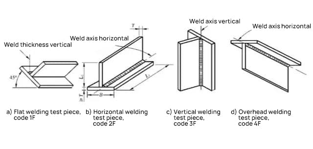
Table 2. Applicable welding positions for test parts
| Test piece | Applicable welding range | ||||
| Butt welding position | Corner welding position | Welding position of tube-plate corner joint | |||
| Form | Code | metal sheets and tubes with an external diameter greater than 600 mm | tubes with an external diameter less than or equal to 600mm | ||
| Sheet Metal Butt Welding (Note A-2) | 1G | Flat | Flat | Flat | / |
| 2G | Flat and horizontal | Flat and horizontal | Flat and horizontal | / | |
| 3G | Flat and vertical | Flat | Flat, horizontal and vertical | / | |
| 4G | Flat and aerial | Flat | Flat, horizontal and suspended | / | |
| Test piece for tube butt welding | 1G | Flat | Flat | Flat | / |
| 2G | Flat and horizontal | Flat and horizontal | Flat and horizontal | / | |
| 5G | Flat, vertical and suspended | Flat, vertical and suspended | Flat, vertical and suspended | / | |
| 5GX | Flat, vertical down and overhead | Flat, vertical down and overhead | Flat, vertical down and overhead | / | |
| 6G | Flat, horizontal, vertical and suspended | Flat, horizontal, vertical and suspended | Flat, horizontal, vertical and suspended | / | |
| 6GX | Flat, vertical down, horizontal and overhead. | Flat, vertical down, horizontal and overhead. | Flat, vertical down, horizontal and suspended | / | |
| Tube-Plate Corner Joint | 2FG | / | / | Flat and horizontal | 2FG |
| 2FRG | / | / | Flat and horizontal | 2FRG 2FG |
|
| 4FG | / | / | Flat, horizontal and suspended | 4FG 2FG |
|
| 5FG | / | / | Flat, horizontal, vertical and suspended | 5FG 2FRG 2FG |
|
| 6FG | / | / | Flat, horizontal, vertical and suspended | All the positions | |
| Welding Sheet Metal Corners | 1F | / | / | Flat | / |
| 2F | / | / | Flat and horizontal | / | |
| 3F | / | / | Flat, horizontal and vertical | / | |
| 4F | / | / | Flat, horizontal and suspended | / | |
| Pipe Corner Welding | 1F | / | / | Flat | / |
| 2F | / | / | Flat and horizontal | / | |
| 2FR | / | / | Flat and horizontal | / | |
| 4F | / | / | Flat, horizontal and suspended | / | |
| 5F | / | / | Flat, vertical, horizontal and aerial. | / | |
Impact of adjusting welding current at different welding positions
The influence of welding current adjustment at different welding positions is mainly reflected on the quality of the weld seam, including penetration depth, fusion width, spatter and porosity. Here are some specific examples:
When the welding current increases (with other conditions unchanged), the penetration depth and reinforcement of the weld seam will increase, while the change in fusion width is not significant or increases slightly. This indicates that in different welding positions, by adjusting the welding current, the shape and size of the weld seam can be controlled.
The size of the welding current directly affects the metal melting speed and the quality of the welded joint. When the current is too high, metal melts quickly, causing deep penetration, large metal spatter, and defects such as burns and undercuts. Therefore, in different welding positions, it is necessary to appropriately adjust the welding current according to the actual situation to ensure the quality of the welding seam.
In CO2/MAG/MIG welding, adjusting the welding current is actually adjusting the wire feed speed, while adjusting the arc voltage changes the wire melting speed. Only when the wire melting speed and feeding speed are equal can welding quality be guaranteed. This suggests that in different welding positions, by accurately adjusting the welding current and arc voltage, uniform melting and wire feeding can be achieved, thereby improving the overall quality of the weld seam.
In shielded secondary welding, current and voltage adjustment are two important factors that affect the quality of the weld seam. They directly determine the penetration depth, fusion width, spatter, porosity and other characteristics of the weld seam. This implies that in different welding positions, by accurately adjusting the current and voltage, the microstructure and macro performance of the weld seam can be effectively controlled.


6 comments
Muito obrigado
Esse manual precisamos em PDF
Boa informação para quem pretende aprofundar os seus conhecimentos sobre soldadura.
Gostei muito do artigo! bem didático e valioso.
Manual interesantè e bastante instrutivo.