Based on the optimization theory of orthogonal test simulation, using the example of a specific thin-walled precision sleeve part, and with machining quality design as the optimization objective, the most important factors that influence the cutting of the part of the sleeve are examined in a best combination of solutions to obtain the ideal process parameters for turning the outer surface.
0. Introduction
“Made in China 2025” has led the manufacturing industry to improve product processing quality requirements. Thin-walled parts are widely used due to their light weight, low consumption cost and other notable advantages. However, as the technology and experience are not yet mature, such products often suffer from deformations in the processing of parts in the production and processing process due to inappropriate cutting parameters, incorrect clamping and tool selection, etc., which affects the quality of the product. Therefore, efficient processing of thin-walled parts has become an urgent need for mechanical engineers to solve engineering and manufacturing problems, attracting countless researchers and scientists to conduct in-depth research and investigation.
M. Hareendran's overseas team not only studied the optimal process parameters for turning thin-walled parts using MATLAB software, but also used ANSYS software to study the part deformation and turning process in depth. Finally, through the virtual simulation of machining errors and actual cutting, it provided a reliable empirical data reference, which is essentially consistent with the practical experience of machining thin-walled parts. S. Sanjeev. Sanjeev et al. used an empirical model for machining H11 tool steel and used the response surface method to identify low-stiffness parts through in-depth study of cutting parameters (cutting speed, feed, depth of cut) and tool parameters. The accuracy and reliability of the model were verified through experiments. Wang Xiangjun's national team etc. used ANSYS software to analyze the optimal process parameters for the thin-walled bearing ring machining process through simulation. The analysis results met the shape and position tolerance requirements of the bearing ring and were able to successfully optimize the work. Xu Guangbin studied thin-walled turning and improved the optimization of the proposed program from the perspective of tool geometry parameters and workpiece clamping on various common thin-walled parts to establish a solid foundation for the machining of thin-walled parts. Deng Zhaoshuai also used Deform-3D, a finite element simulation of different speeds in cutting 45# steel, and studied the effect of cutting speed on the law of tool wear and the relationship between cutting temperature and tool wear to study the tool wear mechanism. , to speed up the cutting process and improve process optimization. To study the tool wear mechanism, an appropriate choice of cutting speed provides a reference basis. In addition, Yue Caixu explained the basic theory of metal cutting finite element simulation technology, technical methods and practical application areas to provide us with better guidance.
Currently, parametric research for turning thin-walled parts is not yet fully developed. CNC turning programming is mainly based on theoretical formulas and empirical data to determine processing parameters, which causes many problems in the production of thin-walled parts. However, with the continuous development of finite element analysis technology, computer-aided engineering (CAE) technology has made it possible to explore the intrinsic mechanism of rotational deformation in depth, and the research results provide strong support for a production of orderly and efficient machining. The digitalization of the image editing and prediction process can not only be realized, but also save a lot of human, material and financial resources, which is advocated by most mechanical engineering scientists and engineers, and gradually creates a wave of research enthusiasm.
In summary, in order to determine the optimal cutting parameters of a thin-walled sleeve, this paper relies on the Naxtran finite element analysis module embedded in NX1899 software to analyze the field of mechanical structure of the cylinder surface turning process of the sleeve and the effects of various orthogonal combinations of machining parameters to examine the deformation of the part. Finally, the optimal parameter combinations for CNC turning are determined to improve the efficiency and accuracy of machining thin-walled parts. Then, the optimal combination of parameters for CNC turning is determined to improve the machining efficiency and accuracy of thin-walled parts.
1. Orthogonal test simulation
1.1 Geometric modeling
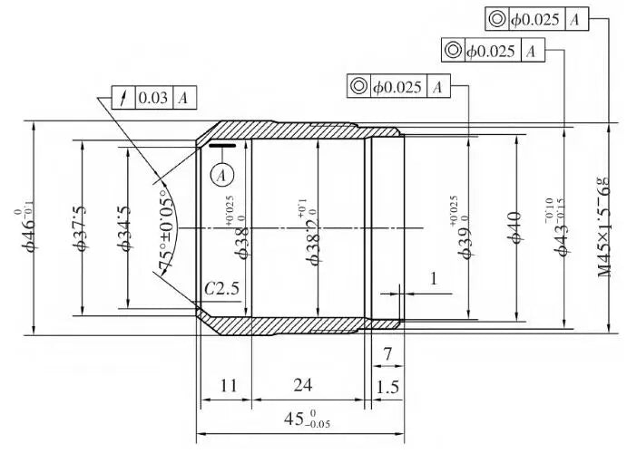
Figure 1 shows the parts that are the subject of this document. The minimum radial wall thickness is only 2 mm on one side. In all machining processes, turning the outer surface of the part has the greatest impact on the rigidity of the part, but it is also a fundamental process to ensure machining precision. Therefore, when optimizing the adjustment parameters, priority is given to studying these working conditions. In this article, the study of the clamping program for thin-walled bushing parts is carried out to determine the use of axial positioning. As shown in Figure 2, the specific part program descriptions and installation steps are not repeated. Under these conditions, it is necessary to simplify processing operations with reference to relevant model static analysis requirements in order to facilitate the acquisition of reliable data results while avoiding tedious simulation calculations. Finally, after completing the axial clamping program after model processing, the finite element analysis module can be called.

Figure 1 Drawing of thin-walled sleeve parts
1.2 Definition of material properties

Figure 2: Part Program Number Model Diagram Axial Fixture
In the FEM environment, the creation of the material intrinsic model refers to the stress-strain relationship curve of the corresponding material, which is used to express the reaction behavior of the material under the action of load. It is one of the three main attributes in CAE structural analysis. In order to effectively determine the deformation of the part in this numerical model, the following simplification is made: It is assumed that all parts of the part material model are 45# isotropic steel, and the actual processing is due to the friction of high temperature generated by the cutting process, caused by the internal metallurgical organization of material changes and the plastic transformation process, is not taken into account to complete the definition of all parts of the program material properties. The main mechanical parameters of the 45# steel material used are a density of 7.83 g/cm 3 Young's modulus of 207 GPa, Poisson's ratio of 0.29 and yield strength of 355 MPa.
1.3 Cellular grid division
The cell grid is the carrier of computational data for CAE simulation and analysis and is an important step in setting up simulation preprocessing. In order to adapt the model mesh partitioning to different parts and various complex structures, this study uses fast and highly adaptive mesh generation. Furthermore, for the complex shape of the wall, it is easier to code the tetrahedral mesh. The mesh cell size is divided into 2mm, and at the same time, the two-surface encryption process associated with the part contact is encrypted to improve the accuracy of data transmission. After the final mesh is completed, the entire finite element mesh model is displayed in Figure 3.

Figure 3: Effect of mesh delimitation
1.4 Configuring orthogonal parameters
Orthogonal design of experiments (also known as DOE design) is a method for designing multifactorial and multilevel tests scientifically, economically and efficiently as a theoretical basis and is used as an efficient design method. It has scientific and reasonable characteristics and uniform dispersion, making it possible to achieve desired testing results with fewer tests, shorter cycles and lower costs. Therefore, this method is increasingly used to better identify the parameters of this program and improve research.
From the perspective of the machining process, there are many factors that affect the accuracy of turning. In addition to the three cutting elements, tool angle, cutting materials, cutting fluid, etc., improper use may cause precision defects, serious chipping or even tool chipping, and machining waste. Therefore, it is obvious that scientific and reasonable selection of cutting parameters is particularly important for turning, especially for machining parts with low rigidity. However, due to limited research time and cost, only the four factors of spindle speed, feed, backward movement and main tool deflection are selected as optimization parameters of this orthogonal experimental design. These parameters are set to three reasonable level values, and theoretical formulas and empirical data are used to set the speed to a low level of 800 rpm, the feed to 0.1 mm/rev, the reverse movement to 0. .3 mm, the main tool deflection to 0.3 mm and the main tool deflection to 0.3 mm. 0.3mm, main tool deflection angle of 45°, realized by four factors and three levels of L 9 (4 3 ) orthogonal test program design, the specific orthogonal test factors and corresponding level values are shown in Table 1.
Table 1 Orthogonal test parameters
| Optimize parameters | Low level (1) | Intermediate level (2) | High level (3) |
| Spindle speed (A) | 800 | 1200 | 1600 |
| Feed speed (B) | 0.1 | 0.2 | 0.3 |
| Overbite (C) | 0.3 | 0.5 | 0.8 |
| Tool main deviation angle (D) | 45 | 75 | 90 |
With regard to the orthogonal test simulation, L 9 (4 3 ) Combination scheme design, see the data in Table 1 for the orthogonal test combination, in which the capital letters correspond to the four different search factors, the number corresponds to the difference in the level of each factor, the establishment of the L 9 (4 3 ) Scheme combination for the four factors and three levels of a total of nine combinations of the test simulation for the main source of calculation of the numerical value of the force cut. In contrast, the shear force can be used for fastening program 2. The shear force can be used to apply the load for fastening scenario 2, completing the design of the orthogonal test parameters between the nine design scenarios.
1.5 Imposition of Load Limitations
Before applying loads and constraints in the simulation setup, all individual parts must be securely connected using the Face to Face command to create the entire simulation analysis. As the entire clamping program relies on clamping the right end surface of the chuck with the three-jaw chuck attached to the machine tool, the use of “custom constraints” in addition to freeing up the rotational degrees of freedom around the axial axis of the chuck everything will be fixed. The load is applied first; the entire part is subject to the gravity of the gravitational field under the action of G. The direction follows the radial direction of the rotating parts; secondly, the centrifugal force of rotation of the device comes from the axis of the central axis of the rotating part, so the center of the central axis serves as the center of the right end surface of the rotating part, and the corresponding value of the rotation load F is added. 1 ; Finally, the thin-walled sleeve parts are also exposed to the main cutting force F due to the radial pressure of the tool. 2 Specific values can be mapped to the corresponding data in the orthogonal test combinations table above. This completes the simulation and load application limitations of a specific axial positioning and clamping program. After configuration is complete, you can begin the hydrostatic solution process.
Referring to the above-described method of applying load constraints to complete the remaining orthogonal test program simulation setup, the specific process is not repeated. Finally, post-processing results corresponding to the nine different scenarios are obtained through repeated simulation setups and a long waiting time. At the same time, after completing the summary of displacement data obtained through calculation and corresponding processing, nine different factors below the level of the average value of the workpiece deformation displacement and three types of extreme difference values are obtained, specifically as shown in Table 2.
Table 2: Orthogonal test of individual program values
| factor | Spindle speed/(rpm -1 ) | Feeding speed/(mm.r -1 ) | Cutting depth/mm | Tool main deviation angle/(°) | Main cutting force/N | Displacement/μm | Tension/MPa |
| Exam 1 | 800 | 0.1 | 0.3 | 45 | 109.9 | 1.13 | 18.77 |
| Attempt 2 | 800 | 0.2 | 0.5 | 75 | 284.9 | 2.91 | 48.65 |
| Exam 3 | 800 | 0.3 | 0.8 | 90 | 612.5 | 6.25 | 104.6 |
| Exam 4 | 1200 | 0.2 | 0.3 | 90 | 169.5 | 1.73 | 28.94 |
| Exam 5 | 1200 | 0.3 | 0.5 | 45 | 417.5 | 4.26 | 71.3 |
| Exam 6 | 1200 | 0.1 | 0.8 | 75 | 271.1 | 2.77 | 46.29 |
| Exam 7 | 1600 | 0.3 | 0.3 | 75 | 231.7 | 2.35 | 39.46 |
| Exam 8 | 1600 | 0.1 | 0.5 | 90 | 167.9 | 1.71 | 28.66 |
| Attempt 9 | 1600 | 0.2 | 0.8 | 45 | 492.8 | 5.02 | 84.15 |
| Average (change) | 3.43 | 1.87 | 1.74 | 3.47 | – | – | – |
| 2.92 | 3.22 | 2.96 | 2.68 | – | – | – | |
| 3.03 | 4.29 | 4.68 | 3.23 | – | – | – | |
| Range | 0.51 | 2.42 | 2.94 | 0.79 | – | – | – |
| Theoretical superiority | A 2 | b 1 | C 1 | D2 | – | – | – |
2. Simulation calculation and analysis
After analyzing the corresponding factors, the average value and the extreme deviation in Table 2, it is found that when reducing the deformation displacement of thin-walled parts, turning is the optimization target parameter. The reverse feed design factor has the greatest influence, followed by the feed, then the main tool deflection angle, and finally the spindle speed. Among them, the influence degree of the main deflection angle of the tool and the rotation speed on the workpiece is similar. In contrast, the influence degree of reverse feed and reverse feed is much greater than the other two factors, which can be tentatively concluded that the appropriate design of feed and reverse feed is the key process parameter that decides to ensure accuracy of the rotation of these thin-walled bushing parts.
Furthermore, by comparing the group average of displacement of each factor to obtain the best level of each factor and the average of the 9 different factor groups, it can be approximately concluded that the theoretical optimal combination under the orthogonal simulation test for A 2 b 1 C 1 D 2 that is different from the 9 groups of data in test combination 1 of the program (A 1 b 1 C 1 D 1 ), and to filter out the best of the theoretically best and orthogonally best combination of two programs, the test theoretically better and orthogonal test were performed under the same static simulation analysis conditions. The final results of the numerical calculation are shown in Figure 4 and Figure 5.

Figure 4 General device displacement map
The numerical calculation results show that under the conditions of a main cutting force of 101.6 N, the theoretically best program has a workpiece deformation displacement of 1.04 μm, which means a reduction in the deformation displacement of about 8% compared to Test program 1. The Von Mises stress value is only 17.35 MPa. It can be concluded that the values calculated from the program are better than the orthogonal tests listed in the nine groups of design options and therefore represent the ideal solution for the thin-walled sleeve. Therefore, the optimal combination of turning parameters for the cylindrical surface of the workpiece for this thin-walled bushing is as follows: when selecting a main tool displacement angle of 75°, the spindle speed is 1200 rpm, the feed is set to 0.1 mm/rev and Return to 0.3 mm.

Fig. 5 Von Mises integral stress clouds
3. Conclusion
Based on test theory and orthogonal analysis, this paper seeks the optimal process parameter combination of spindle speed, feed, return and main tool deflection angle for the machining process of cylindrical turning of thin-walled bushing parts . It is based on NX finite element analysis software to perform structural static field calculation and orthogonal test program analysis sequentially to obtain the displacement and deformation values of parts and their distributions under different process parameters. The relevant conclusions are the following:
- 1) For thin-walled bushing parts, the deformation during cylindrical turning increases significantly with increasing backward movement and increasing feed. Therefore, to ensure the precision and quality of thin-walled parts, these two key factors must be selected scientifically and effectively. However, the influence of the spindle speed and the main deflection angle of the tool on the deformation of the parts is smaller. The supporting role still needs to be chosen wisely.
- 2) The use of orthogonal testing combined with finite elements for thin-walled parts or the combination of orthogonal testing and finite elements provides important theoretical guidelines for formulating process parameters for thin-walled parts while providing a strong guarantee to improve the machining accuracy of parts and reduce the machining deformation of low-rigidity parts. Furthermore, it opens up a new way of thinking and a new method for exploring engineering technology.