Overview
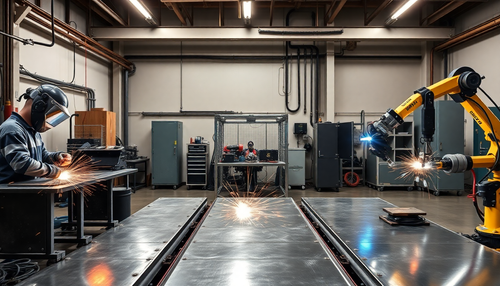
Press braking is performed on items with a high area/volume ratio.
Most sheet metal processed on press brakes is thinner than 6 mm. The machines used to bend metal sheets are called press brakes, which in most cases are hydraulically or electrically driven machines with numerical control.
They are very common in the metalworking area. They work by giving sheet metal an angular or rounded shape through the use of a punch and a concave die.
To define a common lexicon for this manual, let's briefly analyze the components of a press brake.
In the diagram below you can see the components that we will analyze in the following chapters.
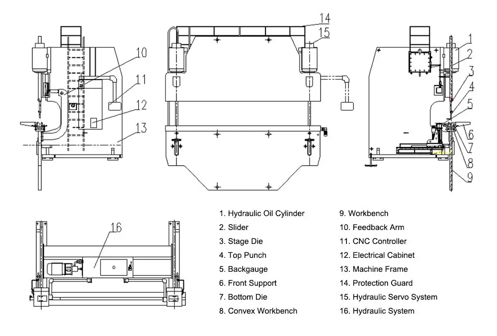
The bending machine is composed of an oil cylinder, a hydraulic system, a grid ruler position feedback system, a ram, a frame and various tools, normally comprises four main components:
- Mechanical Parts – These parts are responsible for the physical movements of the machine, including bending and shaping the metal.
- Electrical parts – These parts control the electrical aspects of the machine, such as powering the engine and operating the lights.
- Hydraulic parts – These parts are responsible for the machine's hydraulic system, which includes the pump, valves, and cylinders that provide the force needed to bend and shape the metal.
- NC/CNC Controller – This component is responsible for controlling and automating the machine, using numerical control (NC) or computerized numerical control (CNC) technology.
Let's explore each part in more detail.
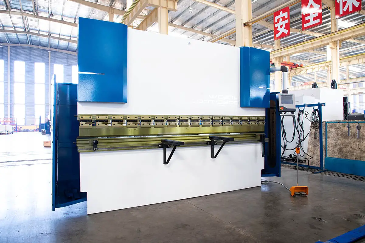
Press the brake body

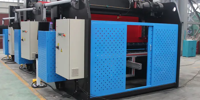
The structure of the press brake is constructed by welding the left and right vertical plates, the work table, the support bodies and the fuel tanks. The work table is positioned below the left and right uprights, while the fuel tank is welded to the uprights.
This design increases the rigidity and resistance of the chassis, in addition to expanding the hydraulic oil heat dissipation area.
Features of press brake structure:
The press brake structure is the structure that supports the ram and is welded to the lower table, generally consisting of two “C” shaped parts at the rear.
- The fully welded structure provides sufficient strength and rigidity.
- The hydraulic oil is transmitted upward, with the cylinders at both ends of the press brake installed on the slider, which directly drives the sliding work.
- The ram uses torsion to ensure synchronization.
- A mechanical stopper is used, providing stability and reliability.
- The ram stroke is adjusted by the controller and can be adjusted manually, with a counter display.
- The wedge-shaped crowning design ensures greater bending precision.
Further reading:
- Press Brake Hydraulic Crowning vs Mechanical Crowning
Press brake controller
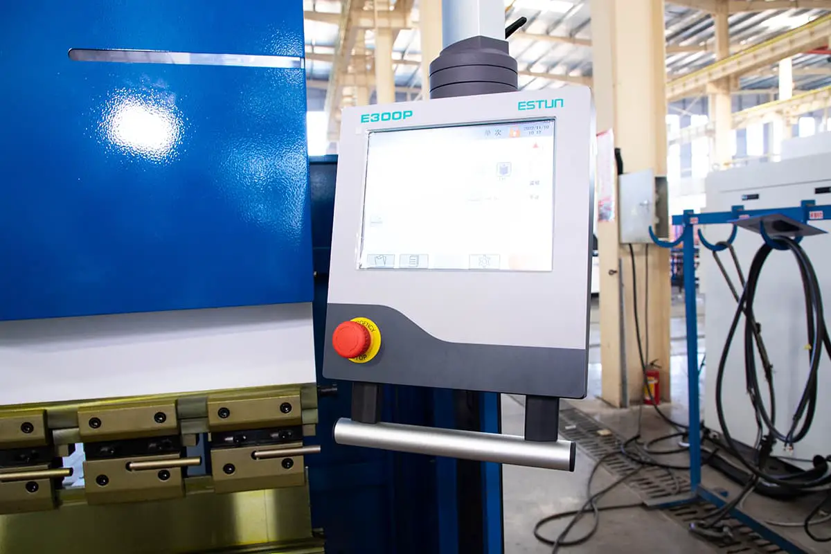
Numerical control of the press brake is a common feature of machine tools.
Numerically controlled machine tools or NC machine tools are machine tools whose operation is controlled by a computer integrated into the machine.
This computer controls the machine's movements and functions according to a specific work program.
Thanks to an encoder in numerical control, it measures the positions of its moving parts and activates actuators (motors, hydraulic pistons or others), which control the machine's movements and position the tool at a specific, arbitrarily chosen point.
A particular machine movement measured by an encoder and controlled by a computer through a motor that can precisely position the machine at an arbitrary point along the available travel is called a controlled axis or simply a machine axis.
In addition to selecting the dimensions or features of a press brake, the buyer can choose from several different types of numerical control, which are mounted on one end of the machine and are the main control point from which programming of the entire system takes place in .
Commercially available types of numerical control differ in the number of axes they can control and the ability to produce a video simulation of the bending sequence.
Press the brake ram
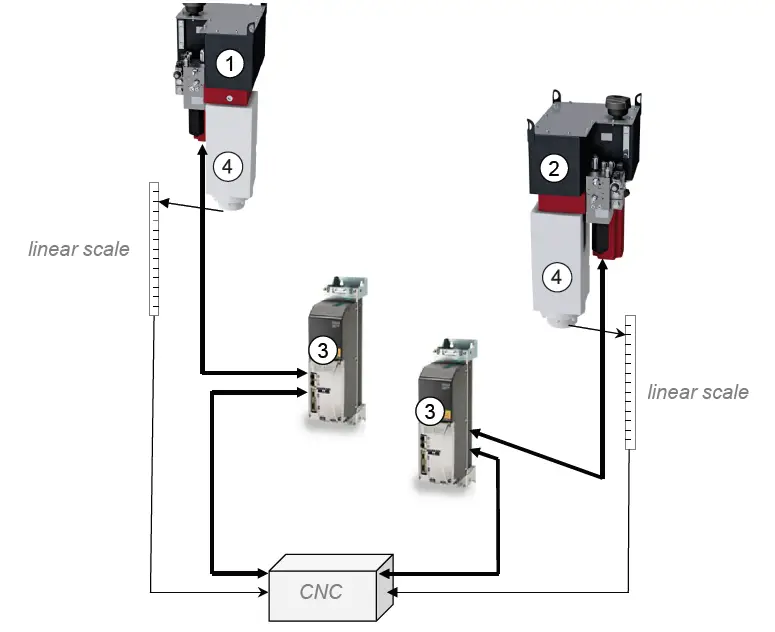
The press brake ram is constructed from a solid steel plate and is connected to the piston rod in the center of the left and right hydraulic cylinders. The cylinder is attached to the connecting plate of the left and right wall plates, and the piston rod is driven by hydraulic power to move the slider up and down.
To ensure accurate positioning of the ram at top dead center, grid rulers are placed on both sides of the ram to transmit position information back to the NC controller, which then adjusts the position. This also ensures synchronized operation of the ram.
The ram uses hydraulic transmission and its system consists of a ram, hydraulic cylinder and a mechanical stop for fine adjustment. The left and right cylinders are attached to the frame, and the piston is driven by hydraulic pressure to move the ram up and down. The mechanical stopper is controlled by numerical control system.
Further reading:
- Press Brake Ram Depth Calculator (Bend Depth)
stroke
The dash indicates the maximum movement available along the Y axis.
dimension is extremely important to check the possibility of using height
punches. In these cases, the operator must check whether: (Natural light – matrix height
(from the base to the lower V) – height of the punch (from the upper beam to the tip of the punch) –
sheet metal thickness < machine stroke.

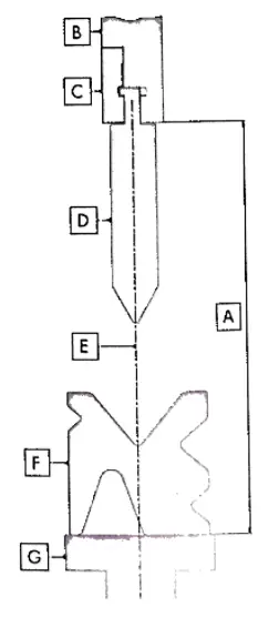
The diagram above shows a cross section of a press brake with a standard Promecam-Amada tool.
- A → natural light: distance between the upper beam and the table
- B → upper beam: upper part of a press brake
- C → upper beam clamp: clamp mounted on the upper beam to hold intermediates
- D → intermediate: part for mounting punches on the upper beam
- E→ intermediate clamp: clamp mounted in the middle to hold punches
- F→ punch: upper tool
- G → machine axis: bending axis that passes through the tip of the punch and the V-shaped center of the die
- H → matrix: bottom tool
- I→ die holder: part for fixing dies
- L→folding table: table for supporting dies.
The image above, on the other hand, shows a press brake with an axial tool (Trumpf, Beyeler, etc...) In this case the punch is fixed directly to the upper beam and the axis of the press brake passes through both the punch and the tip.
- A → natural light: distance between the upper beam and the table
- B → upper beam: upper part of a press brake
- C → upper beam clamp: clamp mounted on the upper beam to hold punches
- D → punch: superior tool
- E→ machine axis: bending axis that passes through the tip of the punch and the V-shaped center of the die
- F → matrix:bottom tool
- G → bending table: table to support the dies.
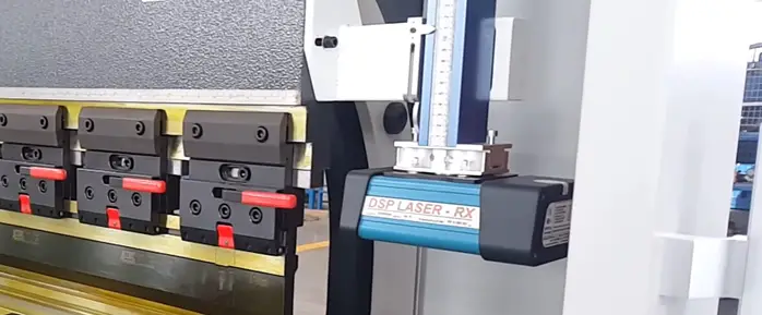
Press Brake Work Table
The back stop moves back and forth through the operation of a motor, and the CNC controller controls its movement distance with a minimum reading of 0.01 mm. There are travel limit switches in the front and rear positions to limit rear stop movement.
Further reading:
- Influence of the hydraulic crowning device of the press brake on the deflection curve of the work table
Synchronization system
The mechanical synchronization mechanism is composed of components such as torsion, swing arm and articulated bearings. It has a simple design, provides stable and reliable performance, and has high synchronization accuracy.
The position of the mechanical stops of the press brake is adjusted through the operation of a motor, and the data is controlled by the CNC controller.
Further reading:
- Brief introduction of CNC press brake synchronous system
Press the brake B Confirmation gauge
| Axle | Description |
|---|---|
| X axis | Controls the forward and backward movement of the rear stop. In systems equipped with an X1 axis, additionally controls the left finger. |
| R axis | Manages the vertical lift (up and down movement) of the rear stop. |
| Z1 and Z2 axes | Responsible for moving the fingers of the left (Z1) and right (Z2) stops, allowing them to move left and right along the rear beam. |
BACK GAUGES are the reference points for positioning the plate. Sheet metal is placed in dies and then pushed against the back gauges. Its movement, governed by numerical control, follows the work program introduced by the operator.
Back gauges can often pivot upward because, during bending, sheet metal can collide with the bottom of a back gauge and lift it up.
However, some types of back gauges ensure that the sheet is always stable for each type of profile.
The back gauge of the CNC press brake uses motorized transmission to achieve synchronized movement through the use of two ball screws and a timing belt. The back gauge distance is controlled by CNC controller.
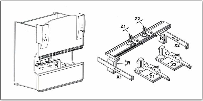
Press the brake shaft:
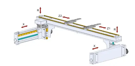
THE MAIN AXES of a press brake are X, Y, Z and R. The X, Y and Z axes can be driven by numerical control or by the operator depending on the characteristics of the press brake.
The bending machine directions in the X, Y and Z axes are indicated by the positive arrow in the figure.
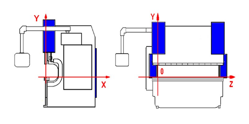
Y axis: the upper beam moves along this axis (up and down) and as it does so, the bending angle changes. During the bending phase, the operator must check that the Y1 and Y2 axes are aligned, as a difference of 0.05mm on a 3m machine would cause a difference of 1° between the two sides of the table.
The operator must therefore check the alignment of the two pistons before starting the bend by zeroing the machine using the appropriate NC button.
If a problem arises, the operator must check the condition of the surface of the upper part, being able to modify the Y axis.
X-axis: This axis determines the bending depth, that is, the distance between the back gauges and the center of the die.
The crossbar where the back gauges are mounted moves along the X axis toward and away from the Y axis.
Z axis: the rear gauges move along the crossbar on which they are mounted and each stop in a specific position depending on the length of the sheet and the part of the press brake where the bend is to be performed (in the middle or to one side of the press press brake).
On a press brake there is a minimum of 2 and a maximum of 4 back gauges. The operator must know the limits of movement along the Z axis, for example the maximum movement allowed along the table or the minimum distance between two back gauges.
R axis: the R axis adjusts the height of the crossbar, so that the rear gauges always adapt to dies with different heights and the sheet always rests on the rear gauges.
Press brake shafts can be categorized as follows:
- Y1: the left cylinder of the ram
- Y2: the right cylinder of the ram
- W: the convex compensation cylinder of the lower beam (i.e. the deflection compensation system)
- X, X1, X2: the back-and-forth meter movement
- R, R1, R2: up and down movement of the rear meter
- Z, Z1, Z2: left-right movement of the back gauge
Note: The piston position can be programmed using an absolute value equation or an angular value.
The location of each press brake control axis is shown in the table below:
| Axle | Zero position | Current value |
|---|---|---|
| Y1 ram to the left (up or down) | Work surface | Distance from table surface to upper die |
| Y2 ram to the right (up or down) | Work surface | Distance from table surface to upper die |
| X、X1、X2 backgauge〔forward and backward〕 | Lower center of the matrix | Maximum distance from bottom die center to back gauge |
| R、R1、R2 backgauge (up and down) | Bottom surface of the matrix | The distance from the lowest point of the back gauge to the highest point of the back gauge |
| Backgauge Z1 left〔Left to right〕 | Left side of the machine | The distance from the left side of the machine to the center of the left rear headstock |
| Right Z2 backgauge (right to left) | Right side of the machine | The distance from the right side of the machine to the center of the left rear headstock |
Press the front brake support
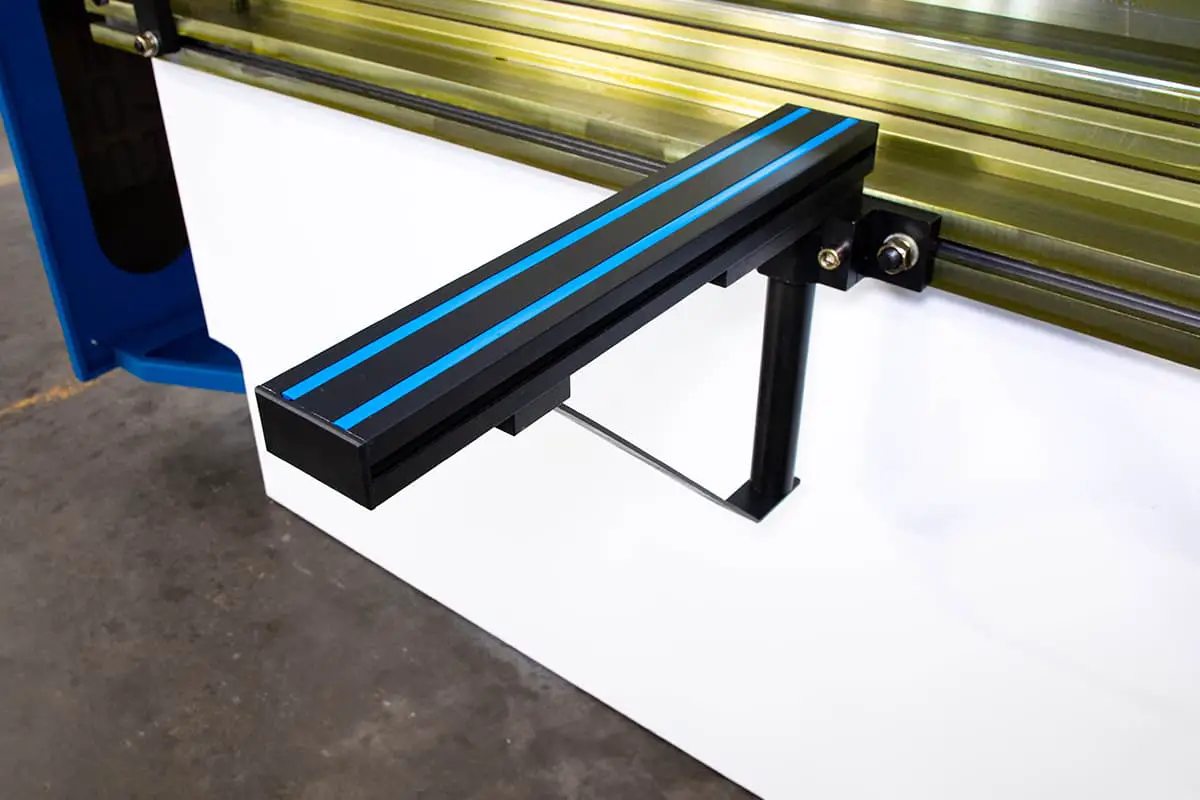
The front support arms of the press brake are fixed to the T-slot or linear guide located at the front of the machine. They are designed with a manually adjustable rear position claw.
FRONT PLATE SUPPORT ARMS are optional equipment that support the sheet during pressing and prevent it from falling during the return of the upper beam.
They are mainly used while bending heavy or large metal sheets but there are different types of support arms to help the operator while bending.
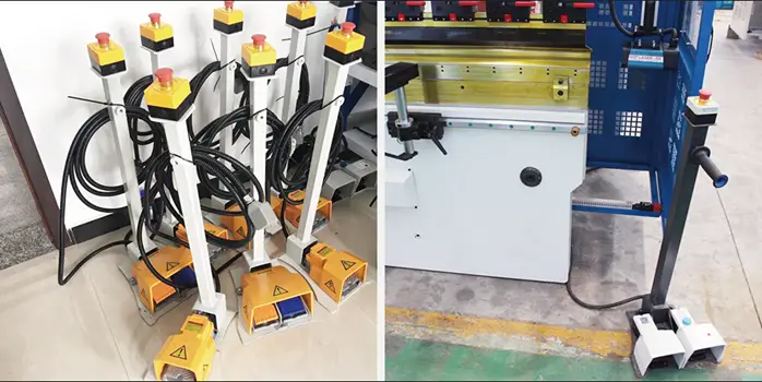
Press the P brake pedal switch
The press brake pedal switch mainly serves to control the movement of the upper punch during the bending operation by raising and lowering it. Additionally, there is an emergency button located on the top of the pedal for emergency situations.
Press Brake Clamps
Press brake clamps consist of standard clamps and quick clamping tools that are used to quickly change the upper punch. The use of quick clamping tools significantly simplifies the process of changing the punch die, making it not only convenient but also time-efficient.

Further reading:
- 2 types of press brake hydraulic automatic clamping design
Sets and accessories
| 1 | User manual | 1 copy |
| two | Foundation Screw | 4 pieces |
| 3 | Washing machine | 4 pieces |
| 4 | oil gun | 1 set |
| 5 | Front Supporter | 2 pieces |
| 6 | Foot switch | 1 set |
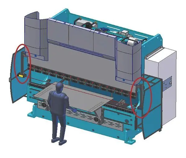
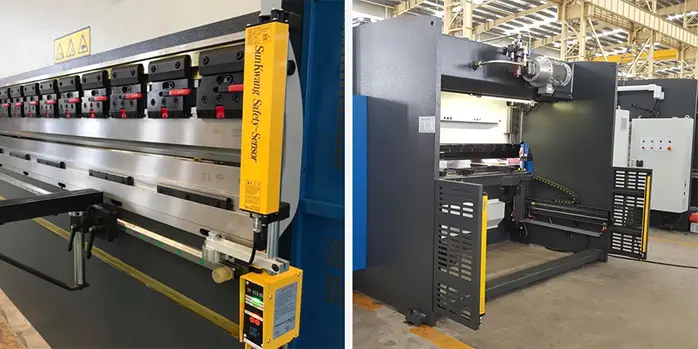
Press brake guard

During press brake, sheet metal is manually moved and positioned by the operator, who is therefore forced to stand very close to a working press brake.
For this reason and to comply with the strict safety standards in force, bending machines are equipped with safety devices, which on the one hand protect the operator's safety, and on the other hand slow down the production cycle.
While the back and sides of a press brake are protected by covers or panels, the front part, which must always be accessible to the operator, is the most dangerous. It can be protected in two different ways: fixed photoelectric protections or laser protection system.
In the first case, two photoelectric protections mounted at each end of the work area protect the entire frontal area up to a distance of 400 mm from the machine. If during the rapid descent of the upper beam, the light beams of the guards detect an object in the working area that is thicker than the material to be bent (for example, the operator's arm), the safety devices interact with the management electronics system and immediately stop the press.
With the laser protection system, only the area close to the tip of the punch is protected. It consists of two photoelectric devices, one for transmission and the other for reception, which can be adjusted manually and which are mounted at each end of the upper beam of the press brake.
They create a beam of light that moves vertically along with the upper beam to which they are attached and therefore only protect the area below the punch.
Normally, the press brake is equipped with a steel fence for the safety of workers. If a higher level of safety is desired, the use of a light curtain safety device and a laser protection device may be considered.
I am aware that a certain degree of safety must be achieved for a machine to be considered safe for use. In light of this, I would recommend equipping the press brake with at least one light curtain device for safety purposes.
Press brake safety guards
Press brake light curtains
Press Brake Laser Guard
Further reading:
- Pressure Brake Safety Tips (Read This for Safety Purposes)
Press Brake Gauge
Commonly used press brake gauges include angle gauges, angle rulers and verniers.

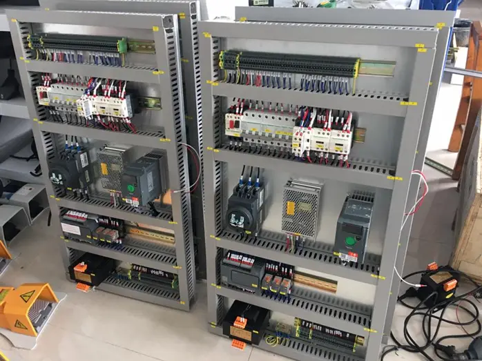
Electric press brake system
The electrical control system consists of an electrical control cabinet, a numerical control system console, and an operator station.
The press brake is powered by a three-phase AC 50 Hz 380 V power supply (which can be customized). This power source can be used not only directly for main motor operation, but also for tail gear servo and equipment lighting after AC voltage output through the system's internal transformer.
The power supply is then transformed into two sets of 24V DC after rectification. One set is used for the CNC controller and the other for the control loop.
Wiring diagram
Different manufacturers may have different designs for their press brake wiring diagrams. At the time of purchase, the supplier must provide the electrical diagram, together with the hydraulic diagram and installation and operation manuals. If they are not included with the machine upon receipt, it is recommended to contact the supplier immediately.
Please note that the following press brake wiring diagram is for reference only and is ours.

Press the brake H Hydraulic system
Development of electro-hydraulic proportional technology
During the latter part of World War II, the speed of jet fighters steadily improved, requiring more advanced control systems with higher requirements for rapidity, dynamic accuracy, and dynamic rate.
In 1940, the first electro-hydraulic servo system appeared on aircraft. In the 1960s, several types of electro-hydraulic servo valves were developed, leading to more mature electro-hydraulic servo technology.
However, in the late 1960s, the demand for electro-hydraulic servo technology in civil engineering was growing, but the traditional electro-hydraulic servo valve had strict requirements for fluid medium and consumed a lot of energy, making it expensive to manufacture and maintain. .
In the 1970s, in order to develop reliable electro-hydraulic servo control technology that met actual engineering needs, electro-hydraulic proportional control technology advanced rapidly. At the same time, industrial servo control technology has also evolved.
Electro-hydraulic proportional technology is a comprehensive approach that combines hydraulic power transmission with the flexibility and precision of electronic control. With the advancement of numerical control technology and the availability of reliable proportional hydraulic components, electro-hydraulic proportional control technology has been widely adopted in recent years, with a typical application being the synchronous control of bending machines.
The basic theory of hydraulic transmission is Pascal's Principle .

The engine, oil pump and valve are connected to the fuel tank. To ensure that the oil tank is adequately supplied with oil during the rapid movement of the ram, a filling valve structure is employed. This not only improves the ram's travel speed but also saves energy.
Hydraulic control of CNC press brakes requires a high degree of automation and standardization in the manufacturing process. As a result, the press brake must integrate the hydraulic system into its design.
The press brake structure serves as the basis for installing the hydraulic components, with the oil tank integrated into the stamping structure.
Three control block style
The press brake has three control blocks. Two of them, with intermediate plate filling valve, are installed directly on the hydraulic cylinder to eliminate the need for piping between the main control block and the hydraulic cylinder.
The back pressure assembly, designed not to leak as required by the customer, consists of a reversible seat valve and two relief valves.
The main components installed in the main assembly include a proportional relief valve, a maximum pressure shut-off valve, and a monitoring system for the reversing valve located at the pilot valve position.
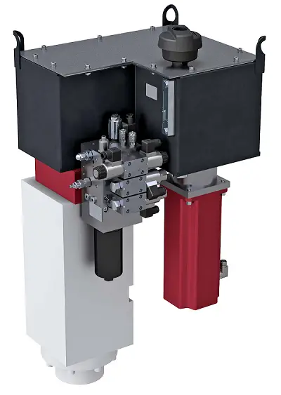
Central Control Block
The central control block combines the three control blocks into one and is mainly used in specialized structures for control purposes. The control block and the connection between the two hydraulic cylinders must be arranged symmetrically.

It uses an SFA series of oil filling valves, designed in a flange structure and installed directly on the hydraulic cylinder, connected to the tank through a suction pipe.
Sensor and Shaft Interface Distributor: All solenoid valves are concentrated in a single control block and the electrical connections of the valves are also centralized in a single cable to facilitate connections. To achieve this, an interface distributor is provided in the central control block.
Hydraulic Oil Cylinder
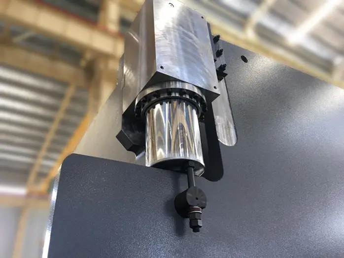
HYDRAULIC CYLINDERS (in hydraulic presses) in which a piston driven by a fluid (oil) under pressure from a pump moves the upper beam (or, rarely, the bench), generating the force necessary for bending. Normally there are two cylinders that move on the Y1 and Y2 axes and must be perfectly parallel to avoid angular differences along the profile.
Further reading:
- What can we do if the hydraulic cylinder doesn't work?
- Hydraulic System Pressure Cylinder Basics
Clean the hydraulic oil
The hydraulic system requires that the hydraulic oil be kept clean. Cleaning the oil tank is crucial.
When replacing the hydraulic oil, the oil tank cap must be removed. Wipe the bottom of the tank with a towel (do not use cotton thread) and then wash it with coal oil gasoline.
Due to the limited reach of the arm to the end of the tank, a towel can be wrapped around a bamboo or stick to clean the corners. The leaking plug or brake valve must be loosened to allow the dirty oil to drain.
Use a cleaning towel to dry the sides and bottom of the tank until it is clean. If necessary, use a ball of dough to collect dirt from welding seams or hard-to-reach areas, then replace the cover.
Further reading:
- Difference Between Hydraulic Oil and Lubricating Oil

Press brake hydraulic oil selection
Recommended hydraulic oil for press brake
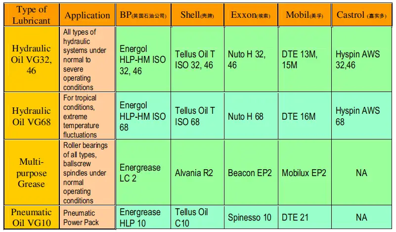
The hydraulic oil brand value represents the average viscosity value at a temperature of 40°C. If the working pressure and temperature of the hydraulic system are higher and the working speeds are slower, a higher brand hydraulic oil should be used.
It is recommended to use ISO VG46# anti-wear hydraulic oil (with an average viscosity of 46mm2/s at 40°C). If the machine operates at temperatures below 5°C for an extended period, ISO VG32# hydraulic oil can be used.
It is not recommended to use the machine at very low temperatures (below -5°C). If this occurs, the machine must be stopped for a while. If necessary, an oil heater can be installed in the circuit.
Under normal working conditions, the oil temperature should not exceed 70°C. Under special conditions, an oil cooler can be installed as required.
Fill the oil
The hydraulic oil used must be clean. To fill in oil, unscrew the air filter nut and fill through the filter. If using filter filling equipment, the oil tank cover can be opened and oil can be filled directly.
Watch the oil gauge and fill oil to 80-90% of the intermediate spaces when the ram stops at top dead center.
To ensure proper operation, the machine must first run at idle speed and then at full speed to eliminate any air bubbles in the hydraulic circuit.
Oil tank capacity
NC Press Brake Oil Tank Capacity Chart
| Model | Oil tank capacity (I) |
|---|---|
| 30t/1600 | 65 |
| 30t/2000 | 65 |
| 40t/2500 | 130 |
| 63t/2500 | 140 |
| 63t/3200 | 150 |
| 80t/2500 | 130 |
| 80t/3200 | 165 |
| 100t/2500 | 230 |
| 100t/3200 | 230 |
| 100t/4000 | 250 |
| 125t/3200 | 220 |
| 125t/4000 | 250 |
| 160t/2500 | 260 |
| 160t/3200 | 260 |
| 160t/4000 | 285 |
| 160t/5000 | 290 |
| 160t/6000 | 300 |
| 200T/3200 | 470 |
| 200T/4000 | 550 |
| 200T/5000 | 550 |
| 200T/6000 | 550 |
| 250T/3200 | 470 |
| 250T/4000 | 540 |
| 250T/5000 | 550 |
| 250T/6000 | 560 |
| 300T/3200 | 540 |
| 300T/4000 | 540 |
| 300T/5000 | 550 |
| 300T/6000 | 560 |
| 400T/4000 | 540 |
| 400T/5000 | 550 |
| 400T/6000 | 550 |
| 500T/4000 | 560 |
| 500T/5000 | 560 |
| 500T/6000 | 620 |
| 500T/7000 | 620 |
| 600T/4000 | 650 |
| 600T/5000 | 650 |
| 600T/6000 | 650 |
| 600T/7000 | 650 |
CNC Press Brake Oil Tank Capacity Chart
| Model | SS tank (I) |
MS Tank (I) |
|---|---|---|
| 40T/1300 | 140 | 150 |
| 63T/1300 | 140 | 150 |
| 63T/2500 | 140 | 260 |
| 80T/2500 | 140 | 260 |
| 100T/3200 | 140 | 260 |
| 100T/4000 | 140 | 260 |
| 125T/3200 | 140 | 260 |
| 125T/4000 | 140 | 260 |
| 160T/3200 | 280 | 370 |
| 160T/4000 | 280 | 370 |
| 220T/3200 | 280 | 420 |
| 220T/4000 | 280 | 420 |
Oil Seal Ring
The oil seal is an important component of the press brake machine.

Goniometers

The goniometers can be mounted on the press brake table or directly on the tools thanks to the magnets they are equipped with. They allow the operator to bend with the sheet positioned at a predefined angle.
Auxiliary mechanism
The auxiliary mechanism is equipped with various functional components that can be selected according to the user's needs, including a worktable compensation mechanism, a backgauge, a quick-release die clamping device, a material conveyor, a oil temperature control system that can cool or heat the oil, a photoelectric protection device, a centralized lubrication system and much more.
Further reading:
- How does the hydraulic system of the press brake work?
- Brake Press Hydraulic System: The Definitive Guide
- Pump Control Technology: Brings Performance Upgrade to Hydraulic Press Brake
Press the brake weight
The weight of the press brake machine can vary from 5T to 300T, which largely depends on the size of the machine. For example, an 80T/2,000mm press brake weighs approximately 6T, while a 2,000T x 12,000mm press brake weighs more than 300T.