Automatic Pneumatic Bumper for Two Wheel Vehicles | Mechanical Project with PDF Report
Roberto Magalhães
Automatic Pneumatic Bumper for Two Wheeler Mechanical Project with PDF Report
This project requires basic knowledge of pneumatic systems and mechatronics .
SYNOPSIS
Pneumatic technology has gained enormous importance in the field of workplace rationalization and automation, from ancient woodworks and coal mines to modern machine shops and space robots. Therefore, it is important that technicians and engineers have a good knowledge of pneumatic systems, pneumatic valves and accessories.
The objective is to design and develop a control system based on an intelligent electronically controlled automotive bumper activation system called “ AUTOMATIC PNEUMATIC BUMPER ”. This system consists of an IR transmitter and receiver circuit, control unit and pneumatic shock absorber system. The IR sensor is used to detect the obstacle. If there is an obstacle closer to the vehicle (less than 4 feet), the control signal is given to the bumper actuation system.
The pneumatic bumper system is used to produce the man and the vehicle. This bumper activation system is only activated at vehicle speeds above 40-50 km per hour. The vehicle's speed is detected by the proximity sensor and this signal is sent to the control unit and the pneumatic bumper actuation system. See also: Automatic Pneumatic Shock Absorber
Introduction
We are pleased to present our new project “AUTOMATIC PNEUMATIC BUMPER” which is fully equipped by IR Sensor Circuit and Pneumatic Bumper Activation Circuit . It is a genuine project, fully equipped and designed for motor vehicles. This is an integral part of the best quality. This product has undergone strenuous testing in our motor vehicles and is good.
See:What is automation?Concept and need for automation
Required components:
1) SINGLE ACTION PNEUMATIC CYLINDER
2) SOLENOID VALVE
3) FLOW CONTROL VALVE
4) IR SENSOR UNIT
5) ARRANGEMENT OF WHEELS AND BRAKES
6) PU CONNECTOR, REDUCER, HOSE COLLAR
7) BOOTH
8) SINGLE-PHASE INDUCTION MOTOR.
block diagram of pneumatic automatic air shock absorber for two wheeler vehicles
Working:
Automatic pneumatic shock absorber operation for two-wheeled vehicles
If the solenoid valve is activated, compressed air passes to the Single Acting Pneumatic Cylinder. The compressed air activates the pneumatic cylinder and moves the piston rod
If the piston moves forward, the braking system will activate. The brake arrangement is used to break the wheel gradually or suddenly due to the movement of the piston. The burst speed is varied by adjusting the valve is called “FLOW CONTROL VALVE”
In our project, we have to apply this breaking arrangement on a wheel as a model. The compressed air taken from the compressor in our project. Compressed air flows through the polyurethane tube to the flow control valve. The flow control valve is connected to the solenoid valve as mentioned in the block diagram.
Download:
Automatic Pneumatic Bumper for Two Wheeler Mechanical Project with PDF Report
Quando se trata de desenvolvimento de jogos e scripts, a escolha da linguagem de programação certa pode fazer toda a diferença. Duas opções populares neste cenário são Lua e JavaScript, cada uma co...
O aço silício é um material fundamental para a indústria de energia elétrica, desempenhando um papel crucial no desempenho e eficiência de transformadores e geradores. Neste artigo, exploraremos em...
Você já se perguntou sobre as diferenças entre o aço inoxidável S30408 e o 304? Nesta postagem do blog, vamos nos aprofundar nas principais distinções entre esses dois materiais comumente usados. N...
A corrosão é um desafio constante para muitas indústrias, especialmente aquelas que operam em ambientes agressivos. No entanto, uma solução inovadora tem se destacado: o aço patinável. Esse materia...
A BYD, marca que começou com a produção de baterias e hoje desafia gigantes globais, está mudando o cenário da indústria automotiva com uma trajetória que exemplifica o poder da inovação e da expan...
Os carros são chamados de "máquinas que mudam o mundo". Como a indústria automobilística tem uma forte correlação industrial, ela é considerada um símbolo importante do nível de desenvolvimento eco...
O titânio é um material fascinante, conhecido por sua resistência, leveza e biocompatibilidade. No entanto, a soldagem desse metal nobre apresenta desafios únicos que exigem técnicas especializadas...
O Banco Central Europeu (BCE) anunciou mais um corte na taxa básica de juros, a sétima redução em um ano, em uma tentativa de sustentar a economia da zona do euro diante das incertezas geradas pela...

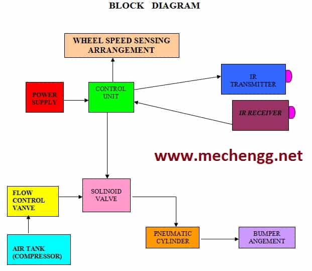 block diagram of pneumatic automatic air shock absorber for two wheeler vehicles
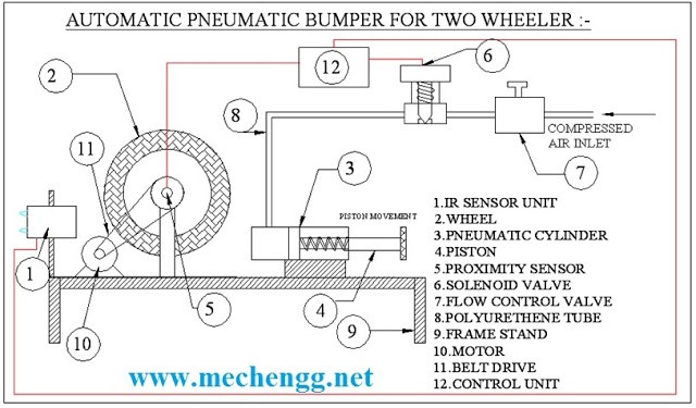 Automatic pneumatic shock absorber operation for two-wheeled vehicles