Functions and Work Ranges
Servonumeric numerical control electro-hydraulic press brake is known for its high efficiency and precision in bending sheet metal.
The size of the V-groove in the bottom die should be adjusted according to the sheet thickness. It is normally greater than 8 times the thickness of the sheet.
Using different types of upper and lower dies, a wide variety of parts can be bent.
To obtain the desired bending force, refer to the sheet metal bending table on the bending machine body or use the bending formula to calculate it.
One pass of the slider results in a bend in the sheet, and complex shapes can be obtained by bending the workpiece several times.
The Hydraulic Press is constructed with steel sheets, providing the necessary strength and rigidity.
Its hydraulic drive prevents the machine from suffering serious overload accidents, even with changes in sheet thickness or incorrect selection of the lower die.
Furthermore, this press brake is known for its stability during operation, ease of use, and reliable safety features.
The connection to the upper die includes a compensation device, which compensates for any deflection of the worktable and slider during bending, ensuring high precision.
It is equipped with electric hydraulic control and adjustable sliding strokes, making it convenient for testing and adjustment purposes.
This bending machine is advanced in technology and reliable in performance, making it an ideal shaping tool.
It is widely used in the aircraft, automobile, shipbuilding and machinery industries due to its high production efficiency.
Lifting and Installation
Elevation
Due to its high center of gravity, the camber brake is heavy at the front and light at the rear. Therefore, care must be taken to ensure the stability of the machine and prevent it from tipping over.
To maintain consistency, silk ropes should be used at a narrow angle of incidence.

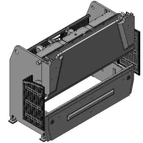
Figure 1
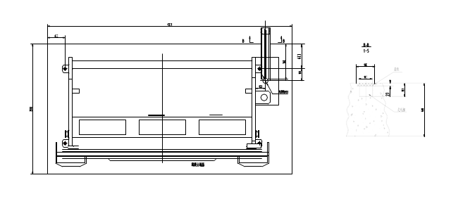
Figure 2
To clean
Before operating the hydraulic press brake, you must get rid of the rust-protective oil on the following moving parts.
- —The surface of the piston post
- —Sliding raster guide rail surface
- —The surface of the guide rail, shaft, supporting the cooking gauge
- —The surface of the sliding guide rail
- —The surface of the work table and mold set
Note: Allow the use of gasoline and coal oil for cleaning, prohibit the use of solvents.
Leveling
Note: The machine must be placed on a level surface before making fine adjustments. Make sure all machine parts, including electrical components, are properly connected before proceeding.
The process is as follows:
- Place the slide block at top dead center.
- Place a gradient (±0.05 mm/m accuracy) on both sides of the slider blocks.
- Adjust the vertical level.
- Adjust the horizontal level by placing a gradient (accuracy ±0.05 mm/m) in the center of the work table.
And in this whole process, the bottom screw must be well connected.
Note: The level should be checked and adjusted again after 30-50 hours of use.
The electrical connections
After connecting the main switch (power phases: R, S, T, PE), check the orientation of the hydraulic pump by performing a brief start-up test. If the orientation is incorrect, immediately turn off the power and swap the two phase lines (see hydraulic pump directional arrow).
The cable entry may be located at the bottom of the electrical box.
Observation:
(1) Make sure voltages are consistent.
(2) It is recommended that a trained electrician or someone familiar with the manual carry out the electrical connection of the machine.
Working theory
The electro-hydraulic servo press brake integrates numerical technology, servo and hydraulic systems. The movement of the control valve causes the upper beam to move up and down periodically, with the movement being measured by rasters on both sides of the machine.
The DNC controls the opening and closing of the two valves on the left and right oil cylinders. If necessary, the servo can reallocate the flow in the oil cylinder, causing the upper beam to move vertically. The movement measurement is determined by the new pulse count. (Figure 3)
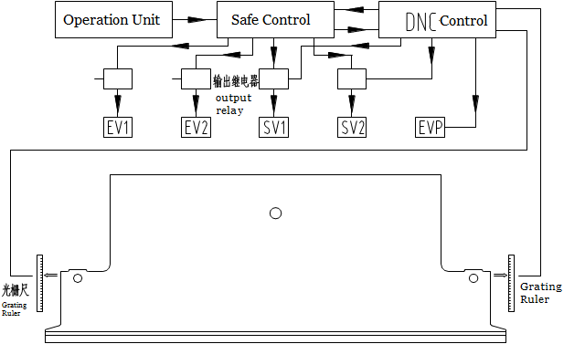
Figure 3
The signal from the DNC controller is transmitted to the servo valve, which converts it into a hydraulic pressure signal and controls the valve movement. Each cylinder in the hydraulic system has its own independent control circuit, which includes the servo valve and the filling valve.
Rear axle
The axis definition
The DNC controls the following axes:
- The left oil cylinder of the sliding block is the Y1 axis.
- The right oil cylinder of the sliding block is the Y2 axis.
- The lower crowning table is the V axis.
- The movement of the back gauge, both forward and backward, is the X axis.
- The movement of the back gauge, up and down, is the R axis.
Note: The slider block position can be programmed using the absolute value equation and angle size.
Manual adjustments or controller control can be applied to the Z1, Z2, R1 and R2 axes.
The position and character of each axis
| Axle | Zero position | Actual numeric value |
|---|---|---|
| Y1 left slider block (up or
(Up or down) |
Work table surface | Distance between worktable surface and sliding block mold |
| Right slide block Y2(up or
(Up or down) |
Work table surface | Distance between worktable surface and sliding block mold |
| Back gauge X、X1、X2
〔front and back〕 |
The center of the lower matrix | Maximum distance between the center of the top
die and back gauge |
| Rear meter R、R1、R2
(up and down) |
Work table surface (and the lowest point of the back gauge) | The distance between the surface of the work table and the lowest point of the back gauge |
| Z1 to the left of the rear meter
〔from left to right〕 |
To the left of the machine body | The distance between the left side of the machine body and the left end of the back gauge |
| Z2 to the right of the rear meter
〔right to left〕 |
To the left of the machine body | The distance between the left side of the machine body and the left end of the back gauge |
Observation:
(1) Follow the instructions in the DNC manual to program the axes.
(2) The terms “left” and “right” in the table refer to the front of the machine when facing it.
Notice:
(1) The operator must be careful about the position of the rear gauge. If it enters the mold area, it may cause damage to the machine.
(2) When adjusting the Z axis manually, do so only from the rear of the machine.
(3) Take care when adjusting the back gauge to avoid hitting the lower die.
The back gauge consists of a beam that extends from one side of the machine to the other, supported by straight guides and lead screws with ball bearings. Rear gauge guides are located on both sides of the machine body, leaving ample room for movement. The X-axis controls the movement of the back gauge through DNC control and is driven by a servo motor.
Press brake hydraulic parts
Hydraulic Pressure Oil Box
The hydraulic pressure oil tank is welded inside the machine body. The inlet is located inside the tank, while the engine, oil pump, high pressure valve, control valve and electronics are located outside. The filter core and valve pedestal are placed at the top, and the oil discharge screw is located at the bottom of the tank.
Electric motor
Four-class three-phase motor
Oil pump
The high pressure gear pump and main motor are connected by a flexible coupling shaft.
The inhaler
The filtration level is 10μm and the maximum pressure is 400 bar. If the filter becomes clogged or the oil needs to be changed, the filter must be replaced.
Synchronized servo valve
The servo valve is mounted on the top of the oil cylinder. Its flow is regulated by the DNC numerical control system and servo amplifier, allowing control of the speed of the sliding block throughout its displacement range. The position and form of control are as follows:
- Fast movement
- Bending speed
- Bottom dead center
- Return trip
- Top dead center
Fill the valve
The servo valve is located at the top of the oil cylinder. When the slider moves quickly, oil flows from the oil box to the cylinder through the filling valve. The valve is closed during the bending process.
Pressure valve
The pressure valve is in the servo valve, back pressure when return is adjustable.
Safeguard
Overrun protection is controlled by the DNC. At startup, the DNC checks the timing and pressure of the oil path for overtaking, also known as the oil pressure leak check.
NC system parameters
Observation:
- 1st, before ordering the machine tool, all parameters must be established by the manufacturer to ensure operational safety.
- 2nd, changes to machine tool parameters can only be made after obtaining approval from the manufacturer.
- 3rd, if the 2nd requirement is not met and changes are made to the machine tool parameters, it may result in accidents with the equipment.
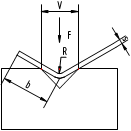
The selection of the lower matrix (see Figure 4)
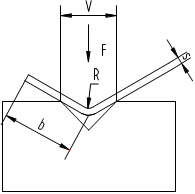
Fig. 4 The lower matrix sketch map
F: The required bending force (KN/m) per meter when the tensile strength of the material is 400 N/mm.
If the tensile strength of the material is 800N/mm, the required bending force (KN/m) per meter doubles. S: Plate thickness (mm)
- S: Plate thickness (mm)
- B: Minimum bending width (mm)
- V: The width of the bottom opening of the die (mm) R: The half bend diameter (mm)
- A: The bending radius (mm)
- V: width of the lower die V, should be determined according to the thickness of the material S and the general formula is: S<3mm V=(6~8) ×S
S<3mm V=(6~8) ×S
S>3mm V=(8~12) ×S
Only by changing the minimum bending width and bending angle can the overall dimension of the die's lower limit be scientifically determined.
| s | V | F | R | B |
|---|---|---|---|---|
| 0.5 | – | – | – | – |
| – | – | – | – | |
| -8 | -28 | -1 | -4 | |
| 1 | 8 | 110 | 1 | 4 |
| 8 | 80 | 1.2 | 5 | |
| 10 | 70 | 1.5 | 6 | |
| 1.2 | 8 | 120 | 1.2 | 5 |
| 10 | 100 | 1.5 | 6 | |
| 12 | 80 | 1.8 | 7 | |
| 1.5 | 10 | 150 | 1.5 | 6 |
| 12 | 130 | 1.8 | 7 | |
| 16 | 90 | 2.4 | 9.5 | |
| two | 12 | 220 | 1.8 | 7 |
| 18 | 170 | 2.4 | 9.5 | |
| 20 | 130 | 3 | 12 | |
| 2.5 | 18 | 250 | 2.5 | 9.5 |
| 20 | 210 | 3 | 12 | |
| 24 | 130 | 3.6 | 15 | |
| 3 | 20 | 300 | 3 | 12 |
| 24 | 250 | 3.6 | 15 | |
| 32 | 190 | 4.8 | 20 | |
| 4 | 24 | 440 | 3.6 | 15 |
| 32 | 340 | 4.8 | 20 | |
| 40 | 270 | 6 | 25 | |
| 5 | 32 | 550 | 4.8 | 20 |
| 40 | 420 | 6 | 25 | |
| 50 | 320 | 7.5 | 32 | |
| 6 | 40 | 600 | 6.5 | 25 |
| 50 | 480 | 8 | 32 | |
| 60 | 400 | 9.5 | 38 | |
| 8 | 50 | 880 | 8 | 32 |
| 60 | 720 | 10 | 38 | |
| 80 | 530 | 12.5 | 51 | |
| 10 | 60 | 1100 | 10 | 38 |
| 80 | 850 | 13 | 51 | |
| 100 | 570 | 16 | 62 | |
| 12 | 80 | 1200 | 13 | 51 |
| 100 | 960 | 16 | 62 | |
| 120 | 800 | 19 | 73 | |
| 14 | 100 | 1310 | 15 | 62 |
| 120 | 1090 | 18 | 73 | |
| 140 | 980 | 21 | 85 | |
| 15 | 100 | 1500 | 15 | 62 |
| 120 | 1250 | 18 | 73 | |
| 140 | 1070 | 21 | 85 | |
| 16 | 120 | 1420 | 18 | 68 |
| 140 | 1230 | 21 | 79 | |
| 160 | 1070 | 24 | 90 | |
| 18 | 140 | 1545 | 21 | 87 |
| 160 | 1350 | 24 | 100 | |
| 180 | 1200 | 27 | 112 | |
| 20 | 140 | 1900 | 25 | 85 |
| 180 | 1700 | 28 | 98 | |
| 200 | 1350 | 38 | 121 | |
| 25 | 180 | 2550 | 28 | 100 |
| 200 | 2100 | 38 | 121 | |
| 250 | 1700 | 41 | 131 | |
| 30 | 200 | 3,000 | 38 | 125 |
| 250 | 2550 | 41 | 131 | |
| 300 | 2100 | 53 | 143 |
During the bending process, the bending force is concentrated on the surface of the work table and acts on the tools at the same time. Therefore, the load that the tooling can support must not exceed its capacity.
For example:
- S=2mm F=150KN (15t/m)
- F=150KN (15t/m)
- B min=10mm R=2mm
- R=2mm
When selecting the lower die, the options are V12, V16 and V20. When choosing V16, it is best to take into account the thickness of the board.
- F=170KN (17t/m)
- Bmin = 9.5mm
- R = 2.4mm
Relatively speaking, the radius is not very significant, and when the bending width (b) is greater than the minimum bending radius, plates of different thicknesses can be processed with the same bottom die.
V16 S = 1.5mm, 2mm, 2.5mm
Note: If it is a molding tool, the bending force should be two or three times greater.
FP= (2….3)Fb
You can also calculate the required tonnage of press brake by Press Brake Bending Force Calculator.
Press Brake Top Punch Selection
The selection of the upper die should also be based on the bending strength and the load capacity should not be exceeded. Furthermore, customers can choose special tools, but they must be aware of the different load capacities compared to standard tools.
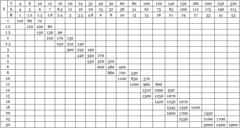
Note: The operator must follow the safety principles in hazardous areas of the machine, as shown in Figures 5 and 6.
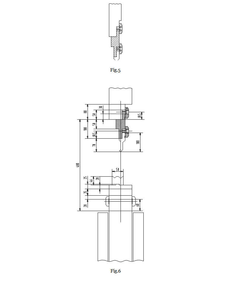
A. It is prohibited to pass through the tooling.
B. To avoid accidents, before installing the upper and lower dies, the start button must be placed in the second control position and the NC drive button must be placed in “shaft stop”.
- Install the lower die and adjust the fixing screws.
- Slowly move the slide block until the distance between it and the bottom die is approximately the thickness of the plate.
- Attach the upper die and upper die pedestal and place them on the slide block. Then, lightly tighten the fixing screws or close the fixing part.
- Apply a small amount of force to align the mold. The top and bottom die centers must be in a straight line. After one edge of the mold is fully connected, tighten the clamping part.
The sheet metal material
The table below is for reference only. If there is any doubt, please refer to the processing material.
| Type | Tensile strength Kg/mm2 | |
|---|---|---|
| Aluminum | Soft stiffness | 10.5 |
| Median | 13.3 | |
| High | 19.6 | |
| Brass | Soft | 32.9 |
| High Strength Mennir Resists Constantan Corrosion | Median | 42 |
| High | 59.5 | |
| Copper | Rolled | 25.9 |
| Chrome aluminum | Soft | 24.5 |
| Heat treatment | 38.5 | |
| Iron | wrought iron | 35 |
| Steel | 0.25%c | 46.9 |
| 0.5%c | 66.5 | |
| 0.75%c | 80.5 | |
| 1.0%c | 91 | |
| 1.2%c | 105 | |
| 1# Steel volume | 52.5 | |
| 18-8 stainless steel | 66.5 | |
Start
Impossible failures and resolution methods
Observation:
Before you start, make sure it won't cause any harm.
The machine tool must be in a safe and suitable condition for operation, with all protective measures and safety devices in place.
Avoid any dangerous operations and follow safety precautions.
If a fault occurs, immediately stop the machine and resolve the problem.
Troubleshooting must be carried out under the supervision of a qualified technician or specialist.
Regularly inspect the exterior of the machine for damage or faults and stop it if necessary.
The operator must read the operating manual carefully.
Problems solution
| Failure | Reasons |
| The press mechanism cannot move quickly | Damaged guide rail movement, damaged EV1/2 switching valve, damaged SV1/2 control valve |
| The press motor cannot produce pressure | EV1/2 replacement did not work, V5/6 fill valve open, pressure adjustment damaged, pump wear |
| The press motor stops in the stop position for 5 to 10 seconds and then moves slowly | EV5/6 filling valve closed, oil position is too low in the oil cylinder |
| The press head moves slightly backwards first and then slowly starts | Single valve V11/V12 open, wrong configuration parameters |
| Fold not correct | Control valve failure, wrong basic configuration, transducer not adjusting well or transducer damaged. |
| The press head cannot go back, the press head goes back slowly | Control valve SV1/2 damaged, switching valve Ev1/2 not responding, fill valve stuck in closed position, single valve EV9/8 in closed position, pressure adjustment valve EVP damaged, incorrect parameter setting, movement of the spang guide rail, the stroke pressure is too low. |
| The press head stopped at the high position, moved back up to 2-3mm, slowly descended, and the speed did not exceed 2mm/min | Open unidirectional V7/8, leakage swap or EV1/2 plug |
Note: A qualified individual is required to resolve any potential faults and comply with inspection and maintenance procedures. During the warranty period, notify maintenance personnel. If the failure is due to incorrect operation, maintenance personnel will not be held responsible.
Press brake machine maintenance
Observation:
- Before the machine runs, it is important that the tools match the control program
Stop the machine after working
Two ways to stop:
- Stopped at the center of bottom dead center
—Move the slide block to the center of bottom dead center
—Close the main engine switch
—Set the operation selection switch to “0”
—Set the main switch to “0”
- Use two wood of the same height to stop (using for maintenance period)
—Place the two pieces of wood on the crafting table
—Turn the “operation selection” switch to “2” (for adjustment)
—Operate in “manual” mode
After the machine stops, move the slide block down by hand until it lightly connects the wood.
—Shut down the main engine
—Change the operation selection switch to “0”
—Set the main switch to “0”
Use the emergency stop button
When pressing this button, all axes will stop and the pump will be turned off, but the control system will remain active. To restart the machine:
—Release the emergency button
—Press the green “main engine operation” button. There is no need to restart the machine tool.
Review the slider block
In the event of a stop, if one side of the slide block is tilted or below the level position, it can be adjusted manually, but the machine must be turned off and restarted under normal conditions.
Note: If the slide lock cannot be corrected or the positioning function fails repeatedly, this may indicate a fault in the control system or hydraulic system.
Maintenance request
The person responsible for maintenance and testing must carefully read the operation manual and have extensive experience.
It is recommended that the manufacturer of this machine carries out a check.
The machine operator must perform a daily inspection for possible leaks or loose parts.
If the user is unable to resolve a malfunction, they must immediately notify the manufacturer.
Maintenance instructions for machine parts.
Weekly Maintenance Checklist:
- Guide lubrication
- Rear gauge lubrication
- Drive belt tightness inspection
- Parallel alignment check
- Cleaning the indicator plate
- Inspection of unit components
- Mold cleaning and damage assessment.
Hydraulic system maintenance instructions
Refilling hydraulic oil:
- Check the oil level daily when the sliding block is at the top. Observe the oil level gauge and top up if necessary.
- If the oil level exceeds 10% of the oil tank capacity, allow the hydraulic oil to circulate in one direction for a time calculated based on the oil tank capacity and hydraulic pump frequency.
- When the sliding block is at top dead center, add oil to the middle of the oil level gauge (visible on the back of the oil tank).
T = V/Q* 5
- T —— Circulation time (minutes)
- V—— Oil box cabling (liter)
- Q——The circulation frequency of the oil pump
High Power Filter
Filter Core Replacement Schedule:
- Replace the filter core after 200 hours of operation, then every 6 months or after 1,000 hours of operation, or when the yellow “replace filter” indicator light comes on.
- The filter requires a 10 micron rating. After replacing the core, allow the oil to circulate for at least one hour as described above.
Note: If the yellow “replace filter” indicator light illuminates, the core must be replaced within 8 hours of operation.
Back gauge
If necessary, the zero position of all machine axes (without rear locator) must be checked weekly or compensated by the DNC.
Inspection of machine operation
Regular inspection items:
- Conveyor measurement system inspection
- Inspection of machine adjustment components
- Bolted connection and rail inspection
- Transducer Signal Transfer Inspection
- Inspection of the sliding block clamping component
- Inspection of the rear meter drive component
- Inspection of the rear gauge clamping component
- Mold Fit Inspection
- Inspection of the thickness of different bending plates.
Inspection of check valves
Valve inspection schedule:
Valves V7, V8, V9 and V10 must be inspected every six months using the following procedures:
- Move the slide block to top dead center
- Disconnect the EV1 and EV2 unidirectional pins
- Operate two manual control switches
- The check valve must prevent oil from flowing from the bottom of the oil cylinder to the oil tank through the servo valve (with the sliding block at top dead center)
- If the slider moves down, contact the manufacturer to replace the valve.
- Move the slide block to top dead center
- Turn off the switch
- Operate EV1 and EV2 one-way valves via the pin on the end cap
- The sliding block must move at a speed of approximately 10 mm/s
- If the slide block moves downward quickly, replace the relevant valve
Note: The check valves mentioned above are part of the safety system. Do not start the machine tool before replacing any potentially damaged valves.
Pressure adjustment valve inspection:
The safety seal ring of the mechanical pressure adjustment valve must be inspected annually.
Note: If the above adjustment cannot be carried out, any claims for compensation for quality problems during the warranty period will be void.
Replacing the oil
Hydraulic oil replacement schedule:
- Replace the hydraulic oil every three years or after 6,000 hours of operation.
- Move the slide block to top dead center and lock it in place.
- Adjust the screw to drain the hydraulic oil.
- Fill new hydraulic oil to the middle level, with the sliding block at top dead center.
- Before restarting the machine, allow the hydraulic oil to circulate for approximately one hour.
- After circulation, insert a 10 micron filter core.
Hydraulic and lubricating oil recommendation
| Manufacturer | Hydraulic oil | Grease |
|---|---|---|
| ESSO | NUTO H46 | LIGHTHOUSE EP2 |
| SHELL | TELUS 46 | ALVÂNIA EP2 |
| GULF | HARMONY 46 AW | CROWN EP2 |
| SHOVEL | ALP 46 | LS2 |
| FEXACO | RANDO OIL 46 | MUTIFAX EP2 |
| MOBILE OIL | MOBILE DTE 25 | LUX EP2 FURNITURE |
Press Brake Safety Labels
Here are the drawings:
Warning Label 1
Warning Label 2
Warning Label 3