I. Press Brake Tools Overview
Press brake tools, widely used in the sheet metal manufacturing industry, are a common tool for sheet metal processing.
Bending tools can be mainly divided into two categories: the upper tool (punch) and its accessories, and the lower tool (die) and its accessories.
The upper tool components include the upper clamp, punch, handle and tool head. The bottom components of the tool consist of the die, die holder, seat and clamps. These components can be combined interchangeably and are made from tool materials.
In operation, the upper tool (punch) presses the sheet surface, while the lower tool (die) restricts it, deforming the sheet into the desired shape. During this process, the sheet bends and deforms, with the inner material of the bent radius being compressed and the outer material stretched.
Inevitably, the tool material and the sheet will suffer friction and compression against each other, leading to irreversible wear of the tool.
The contact surface between the press brake tool material and the workpiece is generally a new surface; the contact pressure is extremely high, sometimes exceeding the yield strength of the processed material.
The contact surface temperature can range from 200°C to 500°C and can reach a peak of 800-1000°C. Tool material wear typically results from a combination of mechanical wear, thermal deformation and chemical effects.
Therefore, when choosing the material of the press brake tool, certain properties must be considered: hardness, heat resistance and wear resistance.
Typically, T8-T12 carbon steel is used, with T10 being the most popular because of its balanced toughness and wear resistance.
After heat treatment, its hardness can exceed 60HRC. Its production is economical, but it has low tempering and heat resistance (up to 250°C). This steel is often used for standard press brake tooling. For superior tool material, 42CrMo high strength alloy structural steel is chosen.
42CrMo is an ultra-high strength steel with excellent strength and toughness. After tempering, it has a high fatigue limit and resistance to multiple impacts and can operate below 500°C. After heat treatment, its ideal hardness is around 45-48HRC.
At present, most CNC press brake tools are made of 42CrMo material. An even better option is Cr12MoV cold work tool steel. Enriched with a good amount of chromium, molybdenum and vanadium, it offers better tempering and hardness.
After quenching, its overall mechanical properties surpass other types of steel, making it suitable for complex, large-section and frequently used cold punching molds. Tools made from it have high precision and longevity, although the material costs are substantially higher.
II. Classification of press brake tools
Press brake tools are auxiliary tools used by press brake machines to shape sheets and process plate materials. These tools consist of several components, with different dies made up of different parts and shapes.
They mainly change the physical state of the material being molded, mainly metal sheets, through the pressure applied by the press brake. This alteration process helps to achieve the desired shape of the material.
Press brake tools can be structurally categorized into two main types: upper dies and lower dies.
In most cases, the upper die is the active (moving) one, while the lower die remains stationary. However, on some bending machines with different operating modes, this can be reversed, but the general concept remains the same.
From a usability point of view, press brake dies can be classified into standard dies and special dies.
Standard top dies generally have tip angles of about 30 degrees (actual angle 26 to 28 degrees), 60 degrees, and range between 78 to 88 degrees.
On the other hand, groove angles for lower dies are approximately 30 degrees, 45 degrees, 60 degrees, and range from 80 to 90 degrees.
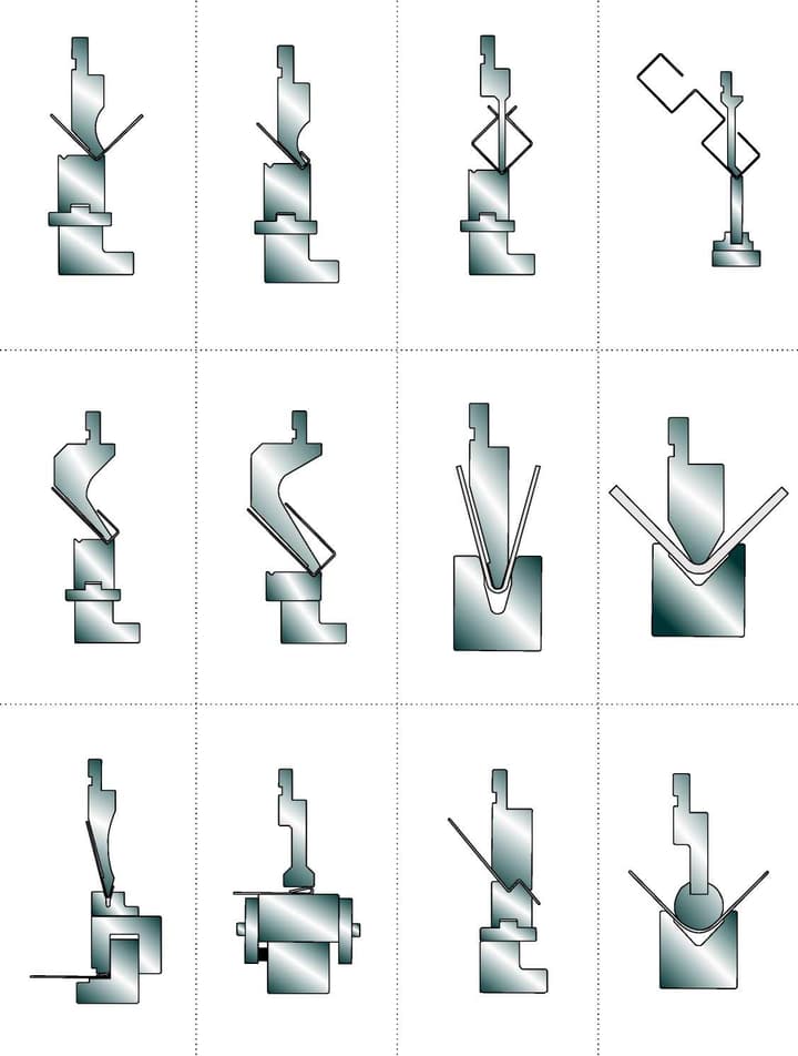
If we categorize top dies based on shape, they can be divided into sharp blade dies, arc dies, bending blade dies, and forming dies.
Typically, sharp blade dies are commonly found with angles of 30 or 60 degrees, with occasional special angles such as 45 or 55 degrees.
Arc dies are mainly designed based on arc diameter and length. Bending blade dies are mainly used for “U” shaped parts or for multi-bend clearance. The most complex are the forming matrices. These can be monolithic or modular.
Generally, modular dies are designed, manufactured and used as an assembly, both upper and lower. The cost of manufacturing monolithic forming dies is considerably higher, especially for larger sizes, and accuracy is more difficult to maintain. Modular matrices present significant advantages for large and complex projects.
In terms of functionality, press brake dies can be categorized into single-function dies and multi-function dies.
Multi-function dies are designed for a specific type of part, while multi-function dies can process multiple types. Some multifunctional dies can be disassembled and reassembled, often called composite dies, such as stepped dies and forming dies.
For lower dies, based on the number of slots, they can be categorized into single V dies, double V dies and multiple V dies. Single and double V dies, as the names suggest, have one or two slots respectively, commonly found on CNC bending machines.
They offer greater precision due to their fixed reference, also known as concentric matrices, and can be interchangeable. Multi V dies generally have multiple slots of various sizes on all four sides, catering to the bending of different sheet thicknesses.
With continuous social advancements and increasing product demands, the requirements for folded products and their materials are also increasing. Press brake tooling continues to evolve with the introduction of built-in bottom dies, unmarked bottom dies, and adjustable opening bottom dies, all of which are widely used across multiple industries.
- Built-in bottom dies mainly improve the utilization rate of die materials or are used to bend special materials.
- Varieties of unmarked inferior dies include ball-type dies, flip-type dies, and polyurethane unmarked dies. Its main objective is to avoid superficial scratches, abrasions and indentation marks on materials.
- Lower dies with adjustable opening come in insertion type, double insertion type, wedge type and rack type. In addition to improving the utilization rate of die materials, they also greatly improve work efficiency and reduce the time and labor involved in changing dies.
III. How to select appropriate tools for CNC press brakes?
A CNC press brake is a mechanical device designed for processing metal materials. When bending metals, you can obtain complex shapes and angles. To obtain different bending shapes, the correct die or tool must be chosen.
Here we will discuss the selection based on the requirements of materials, structure and shape of the tool.
Firstly, the tooling material plays a crucial role in selection. Common tool materials include high-speed steel, alloy tool steel, and tungsten carbide. Each material has its unique characteristics and applications.
For example, high-speed steel tools feature high hardness and wear resistance, ideal for processing small batches of metal. Alloy tool steel is suitable for medium batches due to its commendable hardness and wear resistance. In contrast, tungsten carbide, with its extreme hardness and wear resistance, is perfect for large-scale operations.
Therefore, you should choose tool material based on production demands and batch size.
Secondly, the structure of the tools is another vital factor to consider. Common structures of CNC press brake tools include single-V dies, multi-V dies, and U-die. Single-V dies, with their smaller contact area, are used for smaller bending angles and radii, suitable for heavier metals. thin.
Multi-V dies cater to wider angles and radii with a larger contact area, making them suitable for thicker materials. U-shaped dies, designed for more complex shapes with larger radii of curvature and a considerable contact area, are best for very thick materials.
Therefore, when choosing the tool structure, consider the processing requirements and metal thickness.
Furthermore, the shape requirement of the tooling is essential. Different tool shapes correspond to different bending shapes. Common shapes include right angle dies and radial dies. Right angle dies are accurate in processing right angle bends, while radius dies facilitate various curved shapes. Therefore, the tool shape should be selected based on the processing requirements and metal shapes.
Additionally, consider the precision and wear resistance of the tooling. Precision refers to the dimensional and shape accuracy during processing. Greater precision leads to better quality and accuracy.
Wear resistance means the durability of the tool and its ability to withstand wear and tear during prolonged use. Superior wear resistance can extend tool life and reduce production costs. When selecting the tool, consider the needs for precision and wear resistance.
In conclusion, the selection of appropriate tools requires consideration of material, structure and shape requirements.
You need to align production needs and batch sizes when choosing materials, and align tool structure and shape with processing requirements and metal thickness. Furthermore, precision and wear resistance are vital. By considering these factors holistically, you can select the right tools for superior processing quality and efficiency.
4. What are the common problems with CNC press brake tools?
1. Damage to press brake tools
Damage to CNC press brake tools refers to cracks, breaks and deformations. To solve this problem, it is essential to consider the design, manufacturing process and use of tools.
First of all, it is important to check whether the material used to manufacture the tooling is suitable and whether the corresponding heat treatment process is reasonable.
Normally, the heat treatment process of the tool material greatly influences its durability.
If the hardening temperature of the tool is too high, or the method and duration of hardening are inappropriate, coupled with the tempering frequency, temperature and improper elbow gap selection, the tool may be damaged after entering bending production.
If the size or depth of the clearance hole is insufficient, it may cause blockage, resulting in damage. Underdesigned spring force or unequal height sets can cause spring breakage, drooping, overlapping strikes, and damage to parts.
Improper clamping of the punch or inadequate strength of the screw may cause the punch to fall or break.
When using the press brake tools, errors may occur in the positioning of the part, orientation or inadequate fixation of the screws. If the working height is set too low, or there is insufficient lubrication in the guide columns, or there are malfunctions in the feeding equipment and anomalies in the press, this may cause damage to the tool.
Continuing production without resolving problems such as foreign objects entering the tools, overlapping parts, or clogging debris can easily damage the gap plate, punch, lower template, and tool guide columns.
2. Tool lock
During the bending process, if the press brake tool does not close flexibly or even gets stuck, production must be stopped immediately to identify the cause and correct the problem. Otherwise, the problem could worsen, causing damage to the tool.
The main reasons for tool jamming include tool misorientation, tilting, or the presence of foreign objects that prevent models from aligning flatly; inadequate tool strength or uneven force application causing tool deformation.
For example, if the hardness or thickness of the tool seat or template is too low, it may easily deform upon impact; Misalignment during tool installation, excessive tolerances in the top and bottom positioning of the tool, or poor precision in the press can cause interference.
Insufficient punch force or proximity between large and small punches can cause unbalanced lateral forces on the tool. In these cases, it is advisable to increase the punch strength and improve the orientation protection of the discharge plate.
3. Tool damage and repairs
The cost of tooling for bending production is high, typically representing 1/5 to 1/4 of the total cost of manufactured parts. This is not only due to the high complexity of manufacturing and the cost of tooling, but also the high repair and maintenance costs of sharpening the blade after it is put into production.
The original manufacturing price of the tooling represents only about 40% of the total tooling costs. Therefore, timely tool repairs and preventive maintenance can significantly reduce tooling expenses for bending production.