Geometric Dimensioning and Tolerancing (GD&T) is the standardized system that designers use to communicate tolerance requirements, design intent, and quality guidelines to production personnel.
The symbol of righteousness is an extremely useful GD&T symbol. This article explores the concept of straightness in GD&T, discusses straightness measurement, and the confusing topic of straightness versus flatness.
What is righteousness in GD&T?
Let's briefly explain what righteousness is in general before diving into the details. As the name suggests, it is a GD&T symbol that controls the straightness of a geometric entity. The nature of the unit may vary, as we will soon see, but the basic concept remains unchanged.
In design, straightness tolerance can be applied in several ways. For example, a table needs to be straight enough (or flat, you'll understand the technical difference in a moment) so that the objects on it remain stable and don't roll.
Another example is the inner ring of a bearing. Its surface must be very straight in the axial direction to fit the shaft well. In this case, the lack of straightness can cause misalignment and damage to the bearing.

Warning and symbol of righteousness
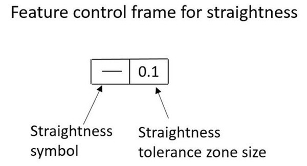
GD&T defines tolerances on a technical drawing in a very standardized way. In this section we present the straightness symbol and its labeling in a technical drawing.
The symbol of righteousness is simply a flat horizontal line – like a dash. The label refers to a surface or size feature. The following figure shows a very simple example.
It is important to note that straightness in GD&T is not relative to a reference point, which is a requirement for other symbols such as parallelism.
Now let's distinguish between the two main ways of using straightness in GD&T: surface straightness and straightness tolerance on a derived centerline.
Surface straightness in GD&T
Surface straightness is often applied to flat or cylindrical surfaces. A tolerance zone for upper and lower deviations is defined along a 2D line on the surface. For flat surfaces, the 2D line can be anywhere on the surface, and for cylindrical surfaces, the 2D line is parallel to the axis.
This surface straightness in GD&T is not obtained through size features, but directly through the reference surface.
How do you measure the straightness of a surface?
Technical verification of surface straightness tolerance requires precision equipment and quality personnel skills. There are two main methods for making surface straightness measurements.

Dial meter
Dial indicators or height gauges are standard equipment for manual straightness measurements. After the dial indicator is properly secured, the contact point of the dial indicator is placed on the surface and then slid over the desired 2D measurement line.
It is important to ensure that the dial is calibrated and zeroed and that the plunger is lightly depressed before starting the measurement. Compliance with these standard procedures ensures accurate measurements.
If the deviation of the dial indicator over the entire measuring length is within the defined tolerance limits, the part has passed quality control.

Coordinate Measuring Machine (CMM)
The other method of making straightness measurements is to use a coordinate measuring machine. This method provides more accurate results than dial indicators. It is an automatic method that requires programming a coordinate measuring machine.
After the part is mounted on the base of the coordinate measuring machine, the measuring probe scans the surface along the reference measurement line and creates an automatic report for the operator indicating whether the part is within tolerance or not.
Centerline straightness derived in GD&T
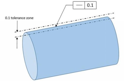
The derived centerline (DML) is the imaginary axis of a part with rotationally symmetric features. Generally this applies to cylindrical shapes. Applying straightness tolerance to a DML controls its straightness by creating a perfect cylindrical tolerance zone around it.
Also note that the tolerance zone in this case is a 3D cylinder around the true axis of the feature. This is useful for detecting twists, folds and other geometric irregularities in the shape of the part.

Furthermore, no reference point is required for this application of the straightness symbol. In GD&T, several symbols require the definition of reference points that can be used as a reference for measurements. For example, the perpendicularity symbol. For an edge to be perpendicular to something, a reference point is needed to measure the perpendicularity. The symbol of righteousness does not require a reference point.
MMC/LMC Notice
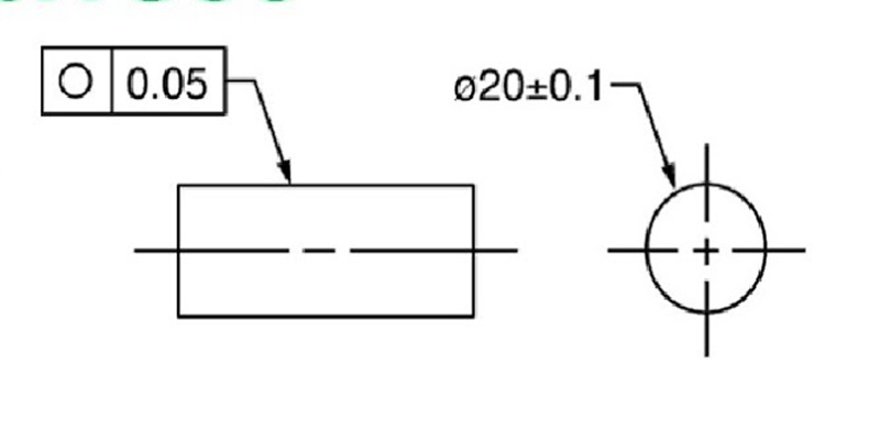
There is a special case for straightness in GD&T in DML cases where engineers use the maximum material state modifier (  ) along with the straightness symbol.
The MMC (Maximum Material Condition) modifier is a function-based designation that aims to ensure that the part does not conflict with its associated components, even under the worst conditions. This is the case when you have the maximum amount of material due to inaccuracies.
For waves, MMC occurs when the wave reaches its maximum possible size. At this size (MMC), the entire shaft must fit into a hole with a diameter equal to the MMC. The formula that combines the three concepts of MMC, straightness tolerance and hole size measurement is:

Suppose we have the following case of righteousness in GD&T labeled MMC.

If we apply the formula along with the GD&T label reference values, we will obtain a cylinder measurement of 10.08. This represents the maximum deviation allowed on the part, which consists of 0.05 of the size tolerance plus 0.03 of the straightness.

Bonus Tolerance
Furthermore, it is important at this point to introduce the concept of bonus tolerance. This applies if the part size is not in its worst condition. In other words, its diameter is less than 10.05, which is the maximum allowed. In this case, the straightness tolerance can be increased as the diameter is smaller than its maximum value, which is 10.05.
For example, if the wave size is 10.03, the bonus tolerance will be 0.02 (10.05 – 10.03). This value is added to the straightness tolerance, which is now 0.05 (0.03 + 0.02).
This is an advanced concept that requires deeper knowledge of MMC/LMC and GD&T in general. However, this simple example shows how straightness behaves in GD&T when used to control a DML along with the MMC call.
How do you measure the straightness of a derived centerline?
The straightness measurement for features derived from the centerline is slightly different from our previous case. The most popular method of taking this measurement is to use a cylindrical gauge with a hole that serves as a quality inspection device.
If the part fits into the hole smoothly and there are no significant problems anywhere, the part has passed the quality test.
Additionally, engineers can also use a coordinate measuring machine. The center of the part is scanned at several points along the axial direction. However, this method is time-consuming and only useful in some cases. In most cases, checking the functionality of the part with a cylinder gauge is a good guarantee of its quality.
Righteousness vs. flatness: what are the differences?
Flatness is a very similar concept to straightness in GD&T, which often causes confusion among designers, production engineers and operators. This section looks at the differences between the two and presents an easy-to-understand comparison between straightness and flatness.
- Line vs. Flat : Simply put, flatness refers to an entire surface, while straightness in GD&T only concerns a line.
- 2D versus 3D : Another way to look at the comparison between straightness and flatness is that flatness controls a 3D object while straightness controls a 2D object.
- Operating functions : The flatness symbol is limited to flat surfaces that must be completely within the tolerance zone. Straightness, on the other hand, gives designers more options because it is applied to lines, edges, axes, and centerlines.
Concluding
Righteousness in GD&T is an important component in an engineering toolkit. It provides engineers the ability to communicate design intent and tolerance requirements to manufacturers and applies to multiple geometric features.
Complete your engineering projects with WayKen

Common questions
What standards are observed when using the symbol of righteousness?
ASME Y14.5 is the gold standard for GD&T, including the straightness symbol. Contains detailed information about the symbol's functionality, its labeling and its use.
Does righteousness require a reference point?
No reference points are required for straightness in GD&T. It is retrieved directly from surfaces and size features.
Can straightness be used to control a surface?
Although straightness theoretically controls the deviation of a surface along a 2D line, it indirectly controls a surface because the theoretical line is defined on the referenced surface. For 3D control of a flat surface, the flatness symbol can be used if possible.