Superior punch selection
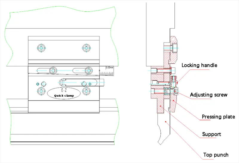
(1) The selection of the upper punch should be based on the bending force, and the die load should not exceed the limit. A punch with hydraulic clamping requires special customization.
If the user chooses special molds, it should be noted that their load differs from that of normal molds. Correct selection must be made to prevent the bending force from exceeding the punch's load limit, which may cause collapse and cracking.
(2) The shape of the upper punch has a significant impact on the ability to bend and shape the workpiece. When programming and selecting the punch, it is essential to consider the shape of the punch and whether it interferes with the part forming process.
(3) When the mold is programmed into the mold library of the CNC system, the overall dimensions of the mold must be programmed accurately. This ensures that when the NC system automatically calculates the bending process, it can accurately determine whether the mold interferes with the workpiece.
Lower matrix selection
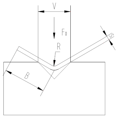
- F0: required bending force per meter when the tensile strength of the material is 450N/mm² (KN/m);
- S: Plate thickness (mm);
- B: Minimum flexion width (mm);
- V: Width of the lower opening of the matrix (mm);
- A: Curvature radius (mm);
(1) The width of the lower V-shaped die should be determined according to the thickness t of the material using the following formula:
If t <3mm, V = (6~8) × t
If t ≥ 3mm, V = (8~12) × t
In addition, the width of the lower die V can be determined based on the minimum bending width b and the fillet radius r of the bent part to ensure reasonable and scientific die selection.
(2) During the bending process, the generated bending force will accumulate on the work table and act on the die. Therefore, the load that the matrix can withstand should not exceed the limit.
The required bending force per meter (T/m) is given in the bending force table, where the tensile strength of the material is assumed to be 45kg/mm² (450N/mm²) and the bottom die opening and plate thickness are predetermined.
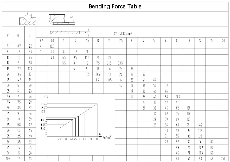
Common Bending Strength Quick Reference Table
When the materials are different, the tensile strength of the material is σ Kg/mm², the required bending force (T/m) per meter can be calculated by the following formula.
F1 = F0 σ/ 450 (T/m)
Note: If the mold is used for forming, the bending force should be 2 to 3 times the normal bending force.
That is:
FP = (2…3) FB
(FP: forming force FB: free bending force)