Arc Welding Inverter Overview
The definition of an arc welding inverter :
The transformation between direct current (DC) and alternating current (AC) is called inversion. The device that carries out this transformation is called an inverter. An inverter that supplies electrical energy to welding arcs and has the electrical performance required for arc welding processes is called an arc welding inverter.
The special nature of arc welding inverter:
The object of the welding power supply is a special arc load, especially for short-circuit transition arc welding, which requires the inverter to withstand the intense dynamic load that is constantly changing. Working conditions are very complex.

Main components and their functions of arc welding inverters
The main components include power supply system, power electronic system, electronic control system, feedback circuit, certain circuit and welding arc.
From the diagram, it can be seen that the main components and their functions of the arc welding inverter are as follows:
Main inverter circuit: Consisting of the power supply system, power electronic system and welding arc, it is responsible for the transmission and conversion of electrical energy.
Electronic control system: Provides sufficient switching pulse signals to the power electronic system (inverter main circuit) according to the variation law required by the arc, driving the operation of the inverter main circuit.
Feedback and system provided: It consists of detection circuit (M), given circuit (G), comparison and amplification circuit (N), etc. Together with the electronic control system, it realizes closed-loop control of the arc welding inverter and allows obtaining the required external and dynamic characteristics.
Arc Welding Inverter Basics
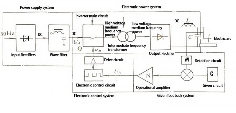
The basic principle of arc welding inverters can be summarized in the block diagram shown in Figure 1.
In the power system, the single-phase (or three-phase) AC mains voltage of 50Hz or 60Hz of 220V (or three-phase 380V) is rectified and filtered by the input rectifier (UR1) and filter (LC1), obtaining a smooth DC voltage of about 310 V (or about 520 V for three-phase rectification), required by the inverter main circuit.
The DC voltage is then converted to high-frequency AC voltage ranging from several kilohertz to two hundred kilohertz by the alternating switching action of high-power electronic switching devices (such as thyristors, transistors, field effect transistors or IGBT) in the main inverter circuit. Q of the power electronic system.
After that, the voltage is reduced to tens of volts suitable for welding through the high (medium) frequency transformer (T), and then the external and dynamic characteristics required by the arc welding process are obtained through the control drive circuit and the feedback and certain circuit (M, G, N, etc.) of the electronic control system, as well as the impedance of the welding circuit.
If direct current is required for welding, the high (medium) frequency AC is converted to DC output by the output rectifier U and the filter of inductance L2 and capacitor C2.
The rectification process of arc welding inverters can be simply described as follows: AC input → rectification to DC → high/medium frequency AC conversion → voltage reduction → AC output → rectification to DC again.
There are three types of inverter structures that can be used in arc welding inverters:
- CA-CC-CA
- CA-CC-CA-CC
- AC-DC-AC-DC-AC (square wave AC).
Electrical output characteristics of arc welding inverters
To meet the requirements of the arc welding process, the electrical output (performance) characteristics of arc welding inverters must have corresponding adaptability. Electrical output characteristics mainly include external characteristics, regulation performance and dynamic characteristics.
1. External characteristics of arc welding inverters
Arc welding inverters use electronic control and voltage-current feedback systems to perform closed-loop control of the power electronic system (inverter), in order to obtain different shapes of external characteristic curves.
Based on the basic principle of the arc welding inverter block diagram (Figure 1), the arc welding inverter closed-loop control system can be described using block diagrams and equations as shown in Figure 2.
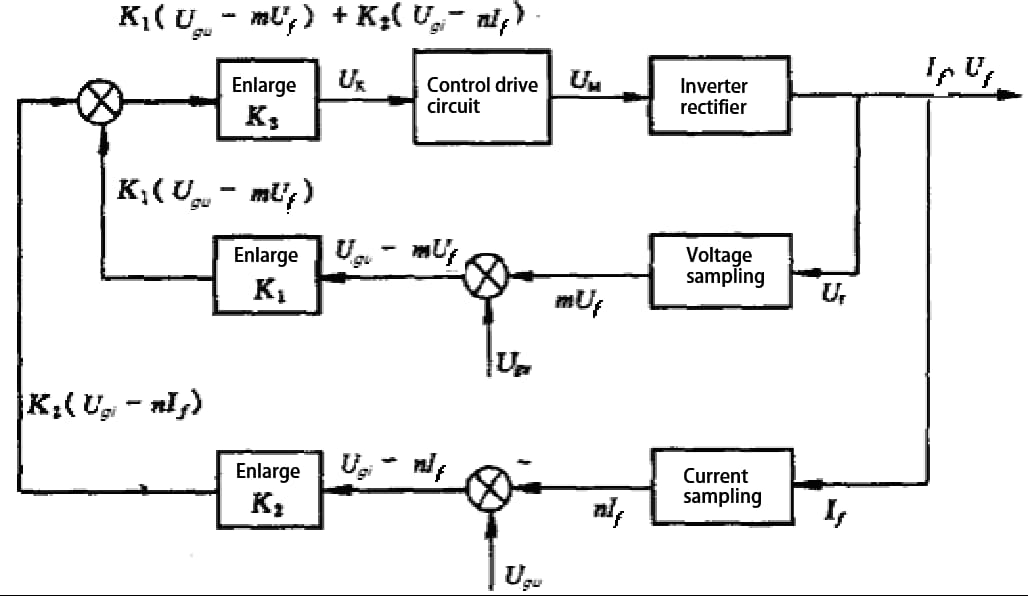
The equilibrium relationship of the closed-loop control system is established as follows: The arc voltage (U f ) is fed back negatively into the diagram, and the output voltage is sampled (usually by a voltage divider) to obtain a quantity of feedback (mU f ) proportional to it. The arc current (I f ) is also negatively fed back, and the output current is sampled (usually by a shunt or Hall element) to obtain a feedback amount (nI f ) proportional to it. The feedback quantities mU f and I f are then compared and amplified with the set value of the arc voltage (U face ) and the set value of the arc current (U welded ) respectively, resulting in K1(U face -mU f ) and K2(U welded -n) outputs. Finally, the control voltage (U k ) is obtained through synthesis and amplification and then inserted into the control drive circuit to trigger the operation of the power electronic system (inverter).
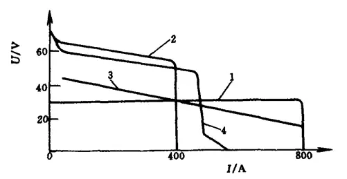
Obtaining the characteristics of constant voltage, constant current and smooth drop:
1 – Constant voltage characteristic
2 – Constant current characteristic
3 – Soft fall characteristic
4 – Constant current with external drag characteristic
2. Regulatory performance of arc welding inverter
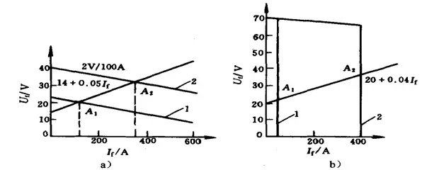
a) Constant voltage characteristic
b) Constant current characteristic
From the principle of the external characteristic curve of the arc welding inverter, it can be inferred that for a certain voltage value of the constant voltage characteristic, the output arc voltage size is determined. In other words, if the given voltage is high, the arc voltage will also be high and vice versa. For example, if Ugu1 < Ugu2, the external characteristic curve moves from curve 1 to curve 2, as shown in Figure 4a, and the stable operating point moves from A1 to A2.
For the constant current characteristic, the size of the voltage value for a given current determines the size of the output welding current. In other words, if the Ugi is large, the output welding current will also be large and vice versa. For example, if Ugi1 < Ugi2, the outer characteristic curve moves from curve 1 to curve 2, as shown in Figure 6-4b, and the stable operating point moves from AI to A2.
Generally, different types of arc welding inverters adopt different regulation systems to achieve control of external characteristics and adjustment of process parameters to meet different requirements of the welding process. We will introduce the working principles of different types of arc welding inverters one by one.
3. Dynamic characteristics of arc welding inverters
When arc welding inverters are used for arc welding processes with short-circuit transitions involving molten droplets, strict requirements must be imposed on their dynamic characteristics. The main parameter that affects the short-circuit transition of MAG/CO2 welding is the rate of increase of the short-circuit current (di SD /dt), which is directly related to the time constant T (T=L'/R f , where L' is the equivalent inductance of the welding circuit and Rf is the arc resistance). R f varies with the welding current and cannot be changed arbitrarily, while L' can be changed by adding inductors to the welding circuit. Furthermore, the di SD /dt can be changed by adjusting the time constant of the closed-loop system.
There are generally two ways to improve and control the dynamic characteristics of arc welding inverters:
- Adding inductors to the welding circuit. Inductors are typically added not only to improve dynamic characteristics but also for filtering purposes.
- Design electronic inductor arc welding inverters, which use electronic circuits instead of iron core inductors to control the di SD /dt, thus demonstrating their superior control performance.
4. External characteristics, adjustment characteristics and control mode of output pulses
Typically, arc welding inverters use three tuning control modes to control external characteristics, tuning characteristics (process parameter tuning), and form output pulse waveforms:
- Fixed pulse width frequency modulation: the pulse voltage width remains unchanged, and the shape of the external characteristic curve, tuning characteristics (adjustment of process parameters) and output pulse waveform are formed by changing the inverter switching frequency.
- Fixed frequency pulse width modulation: the frequency of the pulse voltage remains unchanged, and the shape of the external characteristic curve, tuning characteristics (adjustment of process parameters) and output pulse waveform are formed by changing the duty cycle (pulse width ratio) of the inverter switching pulse.
- Hybrid tuning: A combination of fixed pulse width frequency modulation and fixed frequency pulse width modulation is used for tuning.
Basic form of the main circuit of an arc welding inverter
Several commonly used basic forms of inverter main circuits are shown in Figure 6.
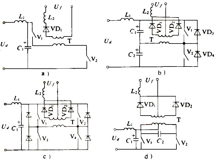
a) Single-ended direct type
b) Half bridge type
c) Full bridge type
d) Parallel type.
Single-ended direct inverter main circuit:
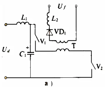
As shown in Figure 6a, the power switching transistors (represented by electronic switch symbols) V1 and V2 are periodically turned on and off at intermediate frequency, thus inverting the input DC voltage into intermittent intermediate frequency voltage. The voltage is then reduced by the intermediate frequency transformer T, rectified by the fast diode VD1, filtered by the inductor and output as DC voltage to the arc. The two switching transistors simultaneously support the input voltage, requiring relatively low voltage resistance, making them suitable for medium and small power inverters.
Half bridge inverter main circuit:
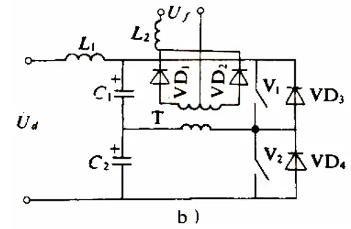
As shown in Figure 6b, the input DC voltage is divided equally between two sets of electrolytic capacitors. The two power switching transistors V1 and V2 are switched on and off alternately to form a rectangular waveform AC voltage.
After being reduced by T, full-wave rectification by VD1 and VD2 produces DC output. VD1 and VD2 must be fast diodes capable of withstanding twice the output voltage amplitude. V1 and V2 only support 1Ud/2 and have relatively low voltage withstand requirements.
Full bridge inverter main circuit:
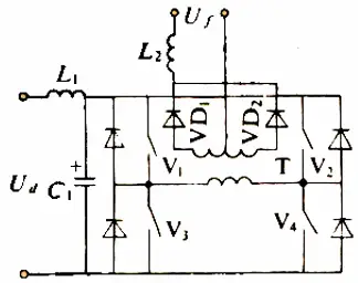
As shown in Figure 6c, two pairs of power switching transistors V1, V4 and V2, V3 on opposite bridge arms are periodically turned on and off at intermediate frequency. The rest of the operation is the same as the half bridge. Power switching transistors also only support a certain voltage, making them suitable for medium to high power welding requirements.
Parallel inverter main circuit:
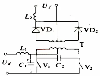
As shown in Figure 6d, this type of main circuit is also known as push-pull inverter main circuit. Power switching transistors V1 and V2 are switched on and off periodically at intermediate frequency.
After being stepped down by T, VD1 and VD2 perform full-wave rectification to output DC voltage. Switching transistors withstand more than twice the voltage, requiring high voltage resistance. Generally, it is only used in thyristor type inverters.
Arc welding inverter control and drive circuit
The electronic control system of an arc welding inverter actually includes electronic control circuits and drive circuits. They are another important component to achieve the electrical performance of the arc welding inverter. Therefore, it is necessary to have in-depth knowledge of the functional requirements of these circuits and how to best meet them.
1. Basic functional requirements for electronic control circuits
The function of the electronic control circuits is to provide a pair of rectangular pulse trains (excluding thyristor inverters) with steep leading and trailing edges, a 180° phase difference, symmetry, and variable width or phase shift to the drive circuit. arc welding. inverter.
For some inverters, such as half-bridge and full-bridge inverters, the pulse trains must be isolated from each other. For a single-ended inverter, only one set of pulses is required.
The design objective is achieved through the relationship between the presence or absence of paired pulse voltages, narrow and wide pulses, the amount of change in pulse width or change in pulse frequency or phase, as well as the relationship between the basic width of the pulse, the minimum pulse width and the speed at which the pulse width increases from the minimum to the nominal width, and the relationship between the minimum and nominal pulse frequency.
More specifically, the control circuit must have the following basic functions:
- The drive circuit provides a pulse train with steep leading and trailing edges, a 180° phase difference, and symmetry. Depending on the inverter type and tuning system, the pulse width can be variable or the frequency can be adjustable.
- The circuit must have sufficient gain to allow the output voltage and current of the arc welding inverter to reach the specified accuracy within the allowable range of changes in input grid voltage and load current.
- Obtain the specified output voltage and current regulation range.
- Implement soft start for input and output voltage.
- It must be capable of generating the electrical performance (external characteristics, tuning characteristics, dynamic characteristics and waveform) required by the arc welding process.
- When the load power (including arc voltage and current) exceeds the rated value, the output power should be automatically limited or the main circuit power supply should be cut off.
- The control circuit must be able to achieve electrical isolation and isolation between the feedback output and input in general cases.
- Turn the main circuit power supply and control circuit power supply on and off in the designed sequence.
- In robotic welding, semi-automatic and automatic welding, the operator must operate the inverter through a remote control box, maintaining a safe distance from the arc welding inverter.
- There must be strong and weak electrical interfaces connected to peripheral devices.
Other functions:
- For bridge or push-pull inverter main circuits, the control circuit must have the ability to automatically balance when there is asymmetry in two half cycles.
- Temperature monitoring (temperature monitoring of key components such as high-power switching tubes and high-frequency transformers).
- Warnings and indications of current limiting, overload and phase loss states must also be considered when necessary.
2. Basic functional requirements for drive circuits
The pulse control signals supplied by the control circuit must have sufficient power. However, due to the different types, models and capacities of switching tubes, the power requirements for inverter pulse signals also differ.
Different types of inverter main circuits also have different isolation requirements for the inverter pulse signals.
For example, in main circuits of full-bridge and half-bridge inverters, switching tubes located at high and low potentials require reliable isolation from inverter pulse signals.
The drive circuits for thyristor- and transistor-based inverters have different characteristics and requirements.
Requirements for the drive circuit of thyristor-based inverters:
- The trigger pulse signal must have sufficient power (voltage and current).
- The trigger pulse signal must be wide enough to ensure reliable conduction of the thyristor.
- The trigger pulse waveform should facilitate thyristor conduction. In a high current thyristor parallel circuit, the parallel components must conduct simultaneously, allowing the switching tube to operate within the allowable range.
- It must be ensured that the thyristor can be reliably switched off when necessary.
Requirements for the drive circuit of transistor-based inverters:
The function of the drive circuit for transistor-based inverters is to amplify the pulse output of the control circuit to a level sufficient to excite high-voltage switching tubes. The amplitude and waveform of the supplied trigger pulse are related to the operating characteristics of the transistor, such as saturation voltage drop, storage time, rate of rise and fall of collector or emitter voltage and current at the time of opening and closure, which directly affect its heat loss and generation.
The drive circuit is one of the main factors that determine the performance of PWM inverters.
Features, classification and applications of arc welding inverters
Features of arc welding inverters:
Compared to traditional arc welding power sources that use a frequency of 50 Hz or 60 Hz to transmit power and change electrical parameters, arc welding inverters increase the frequency to several thousand to two hundred thousand Hz for transmission and conversion power.
This increase in frequency provides arc welding inverters with exceptional characteristics in terms of structure and performance, including high efficiency and energy saving, lightweight and material-saving design, fast dynamic response, and excellent electrical and welding process performance.
Specifically, when compared with traditional arc welding power sources such as arc welding transformers, DC arc welding generators, silicon arc welding rectifiers and thyristor arc welding rectifiers, arc welding inverters have the following significant features and advantages:
- High Efficiency and Energy Saving: With an efficiency rate of 80% to 92%, arc welding inverters can save up to 20% to 35% of energy (varies depending on load size) and have minimal power consumption. no-load power, typically only a few tens to a few hundred watts, which represents only a small fraction of traditional power sources for arc welding.
- Lightweight and compact design: the weight of the medium frequency transformer is only a small fraction of that of the traditional arc welding power source, typically 1/10 to 1/3, and its volume is only 1/5 to 1/3 , making it very convenient to move around.
- Excellent electrical performance.
- Excellent welding process performance.
Classification of arc welding inverters:
Arc welding inverters can be classified in different ways:
- Based on the different high power switching devices used, common types include:
- Thyristor arc welding inverters (SCR)
- Transistorized Arc Welding Inverters (GTR)
- Field Effect Transistor (MOSFET) Arc Welding Inverters
- Insulated Gate Bipolar Transistor (IGBT) Arc Welding Inverters
- Other types such as IGH, GTO, SITH, MCT and MGT arc welding inverters have emerged with the advent of new power switching devices.
- Based on the different types of output current, they can be classified as:
- DC Arc Welding Inverters
- Pulsed arc welding inverters
- Low Frequency Pulsed Arc Welding Inverters
- Medium Frequency Pulsed Arc Welding Inverters
- High Frequency Pulsed Arc Welding Inverters
- Rectangular Wave AC Arc Welding Inverters
- Based on different formats of output characteristics, they can be classified as:
- Constant Current Arc Welding Inverters
- Constant Voltage Arc Welding Inverters
- Slow descent characteristic (including constant current plus external drag) arc welding inverters
- Multi-feature arc welding inverters.
Arc welding inverter applications:
Due to their excellent electrical performance, good control performance, ability to obtain various output characteristic shapes, different types of arc voltage and current waveforms (DC, pulse, AC rectangular wave) and excellent dynamic characteristics, inverters Arc welding machines can produce welding currents of up to 1000A or more.
Therefore, it can almost replace all existing arc welding power sources and be used for various arc welding methods such as manual metal arc welding, TIG welding, MAG/C02/MIG/flux cored wire welding, welding and plasma arc cutting, submerged arc automatic welding, robotic welding and others.
It can weld various metal materials and alloys, especially in applications with limited work space, high altitude operations or where there is a lack of electrical supply and a need for mobile welding machines.