1. General requirements
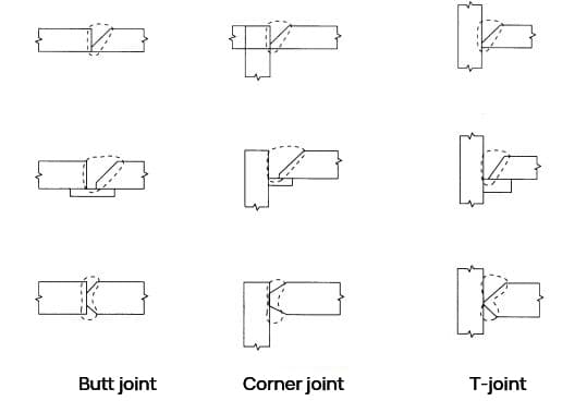
- Figure 1 illustrates that joints welded with first-class full penetration welds can be classified into butt joints, corner joints, and T-joints based on the shape of the component.
Stress transfer welding encompasses full-penetration first-level welds that can handle all types of stress similarly to the base metal, fillet welds that primarily resist shear forces, and partial-penetration second-level welds.
When fully managed, full penetration first level welds excluding low stress and high cycle fatigue, such as crown block beams, are considered to exhibit the same performance as the base metal under all loads, including earthquakes and other loads. repeated in commonly used construction steel. .
- The full penetration first level weld must be fully welded throughout the entire section, and the strength of the welding position must be equal to or greater than that of the base metal.
- The throat thickness of the first level full penetration weld shall not be less than the thickness of the base metal (the thickness of the thinner base metal shall be used if the base metal thicknesses are different and the thickness of the base metal to be welded butt joints must be used if corner joints and T-joints are used).
If the thickness of the throat is less than the thickness of the base metal, it will not only fail to meet the design tolerance, but also become a source of stress concentration.
Similarly, if the welding crown is too high, it will also cause stress concentration, and it is necessary to keep the welding crown at a reasonable size.

- For example, when T-joints and corner joints are subjected to forces that pull the steel plates in the direction of the plate thickness, it is important to note that although there may be no welding defects, the steel plates may still crack due to low resistance. .
It is widely known that the relationship between strength or elongation in the thickness direction and the rolling direction of rolled steel plates is generally reduced.
In particular, when non-metallic inclusions (such as MnS) are deflected during steel rolling, they can crack or peel under very low stresses.
As a result, steel plates used for parts subject to tensile forces in the plate thickness direction, such as the top column flange in the case of column penetration or the beam flange of external columns and corner columns in the case of penetration of beam, must be carefully reviewed and considered.
In continuous casting, differences in solidification temperature or reductions in surface temperature can lead to a deflection of the MnS components in the center of the slab thickness and a tendency towards segregation of Al2O3 in the surface layer. However, these problems have improved in recent years.
Recently, with the increase in the scale of construction, there have been several reports of lamellar weld cracks due to multilayer welding of thick steel sheets.
First-class T-type full penetration weld joints are typically used in the column beam joints of steel structures that experience maximum stress and repeated plastic deformation. This part is the most susceptible to cracking when welding layers.
Therefore, it is necessary to select a high-quality steel plate, review the welding design and construction methods, and pay close attention to preheat management to avoid low-temperature cracking of other heat-affected parts.
2. Slot shape
The shape of the groove in the welded joint is a crucial factor in the stability of both sides of the joint.
Incorrect root clearance or groove angle can negatively impact the quality of the welded joint.
Therefore, it is important to determine the appropriate groove shape based on the type of welding method and joint used.
For conventional welding methods, the standard groove shape for the joint type and root surface size is acceptable as long as the root surface size is less than 2 mm when using a backing plate.
For specialized welding methods or joint types, data must be evaluated to ensure the groove shape meets quality and construction standards based on your specific conditions.
3. Welding crown
To avoid stress concentration, the weld crown in the first level full penetration weld should not be excessively pronounced. The welding crown must have a smooth and uninterrupted surface from the base metal, with a height varying from 0 to 3mm.
4. T-joint crown height
The welding crown on T-joints should reduce stress concentration around the welding area, which is crucial to prevent cracking or chipping of the butt plate. The desired welding crown is shown in Figure 2 and it is important that the weld bead is smooth. The height of the welding crown (h) should be 1/4 of the butt joint thickness, or 10mm if the thickness exceeds 40mm.

5. Passage board
Poor penetration or air holes are commonly seen at the beginning of welding, while crater cracks and other defects often appear at the end. To avoid such defects in effective welding, a suitably shaped steel plate should be placed at the beginning and end of welding as shown in Fig.
There is no need to remove the laying plate after welding and its residue is not problematic, as shown in Fig. 4. However, if the thickness of the slab exceeds 50mm and the column and beam are the same width, it must be cut .
For example, when the crown block beam experiences low stress and high cycle fatigue, it must be cut and refined using a grinding machine.
It is not recommended to directly assemble and weld the passage plate to the column beam joint. This is because the short weld bead created during through flange assembly welding reduces the fracture toughness of the heat affected area, potentially making it the starting point of brittle failure of the entire flange plate.
Fig. 5 provides an example of assembling the arc strike plate and welding at the column beam joint.

The pass-through plate device is mounted and welded to the backing plate. If it is unavoidable to do so in the groove, the construction must fully guarantee the quality of the welded part after positive welding. However, in practice, construction conditions are more stringent than direct welding, resulting in inadequate assembly welding quality.
It is necessary to remove or re-melt the weld bead from the assembly during direct welding, especially for critical joints such as full penetration welding, using one of the following methods:
- Remove the weld bead from the gas arc assembly before welding.
- Use a backhoe to remove welding residue from the assembly at the first end of the weld.
- Re-melt the assembled weld bead without residual defects.
Assembly welding is performed using electric or gas shielded welding. When welding thicker steel plates with a shorter weld bead length, the welding part may harden by rapid heating and cooling and cracking may occur due to the amount of diffusible hydrogen and the degree of restriction. This trend is more pronounced with thicker plates or with higher alloy composition.
Therefore, low hydrogen electrodes should be used for assembly welding with covered electric welding, based on the plate thickness and steel type. However, it may be difficult to change the electrode depending on the thickness and type of steel, so it is recommended to consistently use low-hydrogen electrodes when using covered electric welding.
Gas shielded welding is also effective in preventing cracking due to its low-diffusion hydrogen gas and should be used in assembly welding. Preheating is also effective in preventing cracking and should be conducted under the same conditions as normal welding during assembly and welding.
Other methods to replace the bedplate method include the use of fixed sintered bedplates made of flux, ceramic or stamped steel plates, or the use of the backplate method, back welding method, butt removal method and other methods to eliminate runoff. -on plates.
This method is applicable for flat welding and Q235 and Q345 steels. However, if the weldability test confirms that the quality of the welded part is equal to or greater than that of the steel plate construction method, it may be used outside this scope.
The welding technician must be qualified in the equivalent welding method and recognized by the project supervisor through additional welding technology examination for the equivalent plate execution method.
The most common considerations for fixed-type flaps in construction methods are described below:
- To maintain the performance of the joint, the material of the fixed-type pass-through tab should not interfere with the welding metal in the welding position.
- The backing plate is installed to prevent the weld metal from dripping at the end of the welding process and should extend about 10 mm from the end of the base metal.
- The fixed type snap tab is securely attached to the base metal using methods such as steel wire or magnetic fittings.
As for the welding method, as illustrated in Fig. 6, the arc is started at the point where the end of the base metal enters 15-20 mm and then returns to ensure full penetration into the end during the initial layer of welding.
6. Joints with different sheet thicknesses
When the materials used for welding butt joints have different thicknesses, welding must be carried out from the thinnest material to the thickest to ensure a smooth distribution of stresses.
As shown in Fig. 7(a), when the thickness difference exceeds 10 mm due to the variation of plate thickness or when the crowning block beam is subjected to low pressure and high cyclic fatigue, the thicker plate should be tilted by less than 1/2.5 and the groove should be thinner. The sheets must be at the same height.
However, as illustrated in Figure 7(b), when welding the wing plate joint of an SRC beam formed through an arc head on both sides (backhoe), if the difference in plate thickness exceeds 10 mm, the reinforcement fillet welding should be used.
It should also be noted that one-sided welding of the backing plate must be approved by the project supervisor.

7. Air scratches
When welding on both sides, air gouging should be carried out as a general principle before welding the first layer on the back.
The first layer of surface welding is often prone to defects such as cracking, poor penetration and slag inclusion due to its rapid cooling speed. To solve these problems, air gouging is required to remove any defects in the first surface layer.
However, if a construction test or non-destructive inspection is used during submerged arc welding to verify that the first layer on the back has good penetration, air gouging can be omitted.
8. Backing plate
To ensure adequate root penetration when using a backer plate, sufficient clearance must be provided to ensure a tight connection. If the backing plate is not completely tightened and the root gap is too small, this may result in welding defects such as poor penetration or slag inclusion at the root.
The backing plate should generally be made of Q345B material. For other materials, it is important to examine their chemical composition (P, S, Cu, C, etc.) to confirm that they are suitable for welding.
In general, the backing plate for the column beam joint should be installed inside the side plate. However, the bottom flange plate can be installed externally if required for on-site welding. The position of the backing plate is shown in Figure 8.
Backplate assembly welding is subject to lower tensile stresses and bending stresses, with fillet welding experiencing the maximum stress. This type of welding is relatively simple, but it can also break. In many cases, assembly welding is performed without preheating fillet welding.
Although the original length of the weld bead may be sufficient, the fracture toughness of the weld metal or heat affected zone (HAZ) is low, which may lead to brittle failure of the entire joint if the fillet weld fractures.
As a result, mounting and welding of the bearing plate at the column beam joint should not be carried out within 10 mm of either end of the beam flange or within 10 mm of the R-tip or fillet weld tip of the web fillet (Figure 9 (1)). Assembly and welding must be carried out in the position of the pass in the plate (Figure 9 (2)) or 1/4 of the width of the beam side plate (Figure 9 (3)). If the passage plate is installed on the outside of the bearing plate or beam flange, it must not be mounted and welded on the outside of the beam flange and column flange (Figure 9 (2)).