Currently, the process of welding studs into a metal base material through various welding methods is widely used in electrical cabinets, household appliances, furniture, automotive parts and various sheet metal parts.
These welding methods can generally be divided into two types: energy storage welding and arc welding.
Energy storage welding is most commonly used to weld pins with smaller diameters. The principle involves releasing the stored energy of a capacitor the moment the pin comes into contact with the base material, causing the area where the pin and base material meet to melt and weld together.
This type of welding is completed instantly and has the advantages of simple operation, small marks on the welding surface, high efficiency, compact equipment and easy portability. Now it is widely used in various fields of thin plate pin welding production.
Arc welding applies voltage through a coil between the pin and the base material. As the pin contacts and then moves away from the base material, a short circuit occurs and an electrical arc is generated.
This high temperature electric arc melts the pin contact surface and the base material. After a while, it is pressed firmly, firmly welding the pin and base material.
This method is mainly used in areas that require higher welding strength, such as automotive parts and sheet steel parts.
According to these two welding methods, we have developed stud welding equipment, including portable stud welding, arc welding equipment, CNC automated stud welding machines, robotic stud welding workstations and automatic stud welding machines. table pins. This article mainly introduces the CNC automated welding machine.
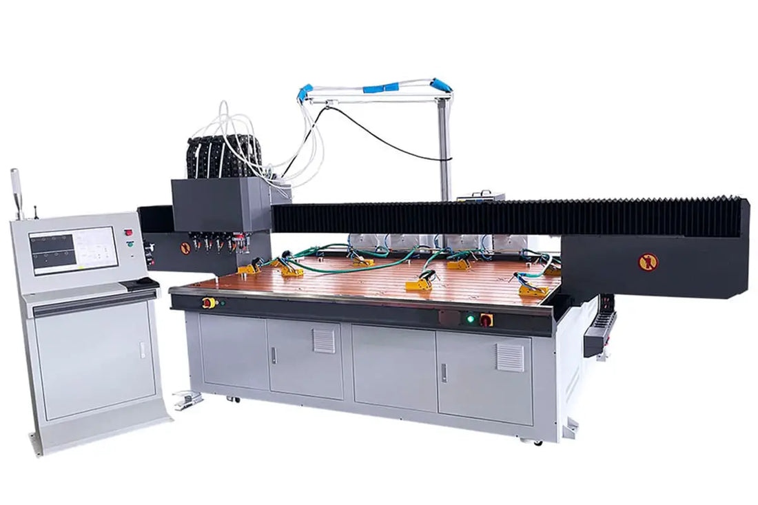
As shown in Figure 1, the automated CNC stud welding machine is an automated device developed to help customers deal with bulk stud welding.
As factory labor costs continue to rise, the variety and quantity of products that need to be pin welded increases, and production tasks tend toward small batches and multiple varieties.
This automated equipment can meet these production needs well and is gradually becoming standard equipment in sheet metal factories and metal processing plants.
Basic Composition of Automated CNC Stud Welding Machine
CNC automated stud welding machine mainly consists of eight parts: rack frame, bed frame, transmission system, drive system, control system, welding platform, automatic nail selection and feeding mechanism, and torch head automatic welding.
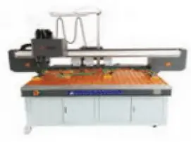
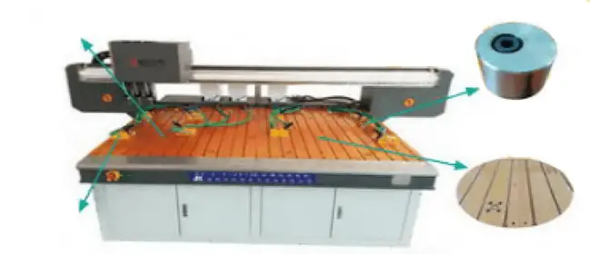
The rack structure is divided into vertical and horizontal structures. Generally, if the length of the part exceeds 3200mm or the width exceeds 1200mm, a vertical frame is used, as shown in Figure 2.
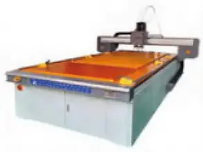
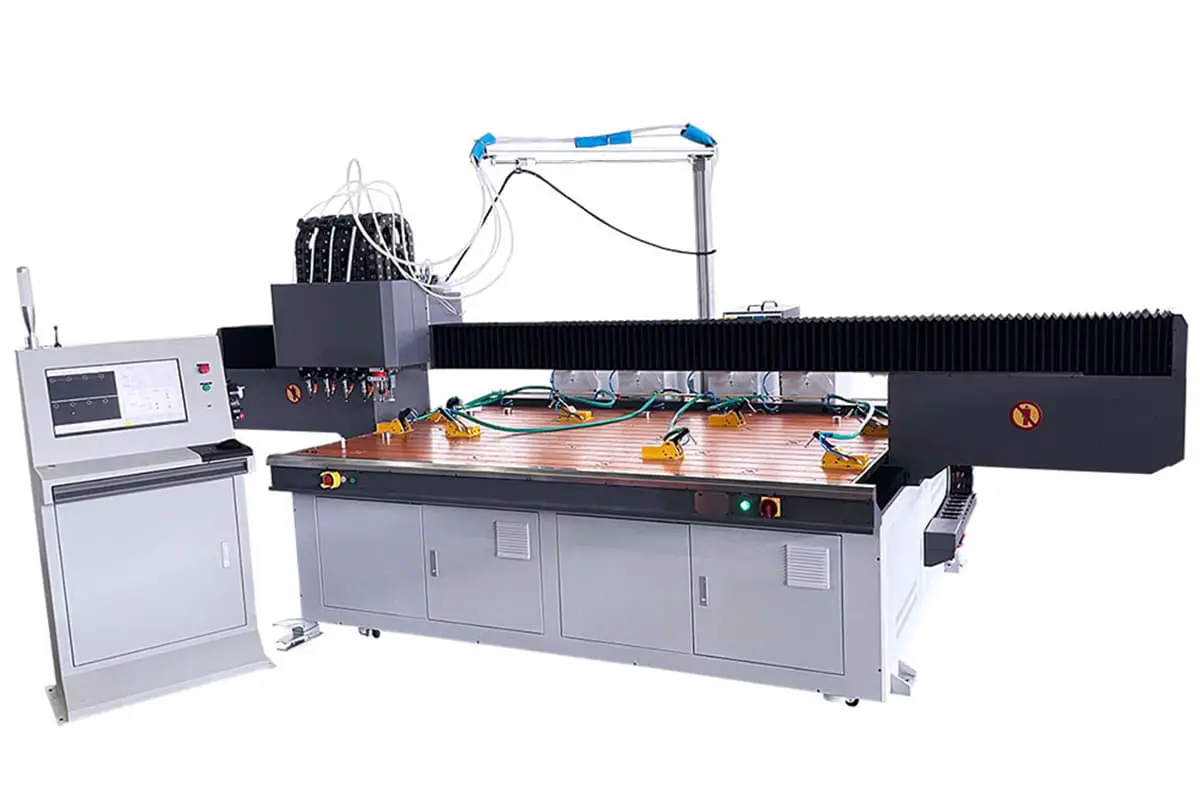
If the length of the part is less than 3200 mm or the width is within 1200 mm, a horizontal frame is used as shown in Figure 3, making it easier to load the part and operate the equipment.
The Y axis adopts a double drive gantry, the X axis beam uses a special extruded aviation aluminum profile, and the moving beam is light, strong and not easily deformed.
The aluminum profile beam is precisely milled by a CNC gantry to ensure that the parallelism and straightness accuracy of the equipment is within 0.02mm.
The direction of the of the effective area of the platform.
Bed frame
Due to the small production volume and high price of this type of equipment, most manufacturers use a square assembly, with a simple structure and low cost.
There are usually two forms: one is assembled from all-aluminum profiles, which is easy to produce and assemble, does not require welding, annealing or precision machining, and has a low production cost.
The disadvantage is that its strength is not sufficient, the structure is subject to deformation, and transportation and handling may lead to inaccurate positioning, resulting in low operating speed of the machine tool.
Another type involves retrofitting the base of a common commercially available engraving machine. There are many manufacturers of these beds and the prices are low. The advantage is that they are easy to produce and assemble without incurring many production costs.
The disadvantage is that the styles of engraving machines are monotonous, generally vertical structures, and due to fierce market competition, the base material and processing control vary widely, making it difficult to guarantee the consistency of product quality.
The equipment we produce uses a base made of resistant steel welded together. After annealing, the installation surfaces of the X and Y axis guide groove are processed by a large gantry CNC milling machine. The machine operates at a stable speed, ensuring excellent product quality.
Transmission system
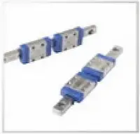
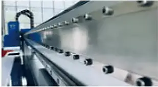
The standard transmission part is equipped with high-precision belt (Figure 4) or rack (Figure 5) for transmission, guided by linear guide rail (Figure 6), ensuring high-precision and high-speed operation.
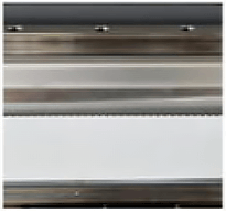

The optional configuration is a linear motor (Figure 7) + metal grid (Figure 8) for transmission.
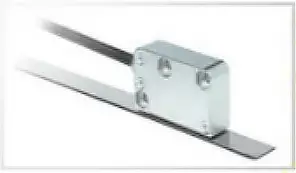
The linear motor has long service life, lower power consumption, more stable transmission and more accurate positioning. It comes with a high-precision magnetic enclosure which is durable, not prone to aging, highly accurate and strong in anti-pollution ability.
Steering system
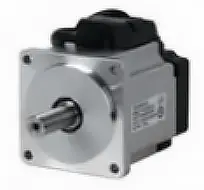
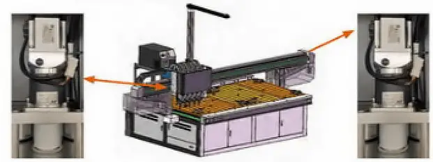
All displacement mechanisms are driven by high-precision servomotors (Figure 9), achieving precise positioning. The Y axis adopts double-drive servo motor control (Figure 10), ensuring high precision and stability during high-speed operation of the equipment.
Control system
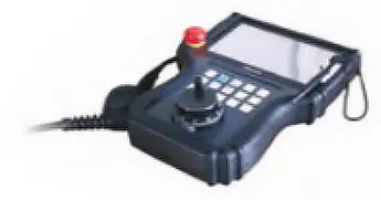
The control system adopts touch teaching integrated numerical control system. The controller is an imported new generation dedicated multi-axis linkage motion controller developed on the basis of industrial robot systems.
It is stable, reliable and powerful. The human-machine interface is a colorful and movable portable box, which is easy to operate, as shown in Figure 11.
The servo motor controller adopts a three-axis system, which is small in size, easy to install, simple to connect and stable in control.
Depending on different customer needs, on-site operating conditions, product batch size and operating habits, we offer three different programming methods: teaching, CAD and coordinates. The system also has practical functions such as riveting and dry running, making operation simple and convenient.
The teaching day is equipped with an infrared indicator. The manipulator's steering wheel is used to position the points, which facilitates the entry of pin coordinates and makes the process practical and quick.
CAD programming can generate work programs from CAD drawings on the computer using specialized software, which can then be copied to the system via USB for direct production.
The coordinate position can be entered into the system table based on machining drawings, allowing the system to generate the processing program. The system also supports program calls by scanning a QR code with a barcode reader.
The system also has a data saving function, which can save all dimensional data of process points, gun head data, etc., into a customized file for easy retrieval.
Welding Platform
The welding platform is composed of a floating ball insulating platform, a pneumatic gripper and a movable positioning block, as shown in Figure 12.
When loading materials manually, the floating ball rises to prevent the workpiece, especially stainless steel workpieces, from scratching the surface due to friction on the insulating platform.
During operation, the floating ball drops and the clamp holds the workpiece securely to the ground. The round movable positioning block makes it easy to clamp any shape of workpiece and can position the outer edge and inner hole of the workpiece.
The workbench is evenly distributed with modular installation dovetail slots, which can adjust the installation position of the pneumatic clamping part positioning block at will. This way, manual loading and unloading saves time and effort.
According to the customer's product requirements, positions A and B can be defined, realizing the alternative use of positions A and B, significantly improving production efficiency.
Automatic nail selection and delivery mechanism
The nail selection and delivery mechanism is divided into a vibrating disc selection and delivery mechanism and a drum-type selection and delivery mechanism, as shown in Figure 13.
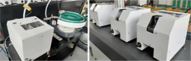
The default configuration is drum type. The vibrating disc is suitable for special pins and the drum type is suitable for common pins.
The automatic nail dispensing device consists of a nail selector, a pneumatic nail dispensing mechanism, an automatic welding gun and a nail dispensing tube.
It can achieve automatic nail delivery and welding, has high reliability in nail delivery, can automatically detect the presence of nails, improves system efficiency and reliability, and has a simple and reasonable design structure that is stable and reliable.
The dedicated nail delivery mechanism has features such as large load capacity, low noise and energy saving and consumption reduction. Nail specifications range from M3 to M8 (non-standard can be customized).
Automatic welding gun head
As shown in Figure 14, the automatic welding gun head uses a servo motor (stroke 150 mm) and a precision sliding cylinder (direct gun stroke 50 mm, oblique gun stroke 150 mm) to move the welding gun mechanism. welding.
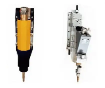
This ensures that the welding height of the welding gun head is adjustable in the range of 0-200mm or 0-300mm.
The distance between the pin and the sheet metal can be adjusted through the servo motor, and the lifting height of the welding gun mechanism can be adjusted according to the shape of the sheet metal to avoid collisions between the workpiece and the gun of welding.
Different welding guns can also be used to adjust the gap between the pin and sheet metal when welding pins of different lengths, ensuring stable and adjustable welding speed and pressure to accommodate uneven sheet metal surfaces.
Features and advantages of CNC automatic welding machine
(1) Precise positioning: Uses computer programming control for flexible, convenient and stable positioning.
(2) High welding quality: It can weld pins of various specifications quickly and firmly to metal surfaces, leaving no traces on the back of the welded plate and no noticeable depression or protrusion.
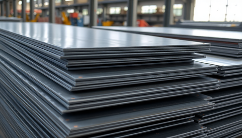
(3) Wide material adaptability: Capable of welding cold plates, stainless steel, aluminum plates, galvanized plates and other materials, as shown in Figure 15.
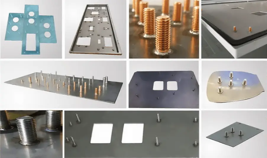
(4) High efficiency: Provides automatic pin feeding and welding, eliminating the need for tedious traditional processes such as drilling, riveting, arc welding and post-welding treatment. It can weld 25-30 pins per minute, saving time and effort.
(5) CNC Programming: Can meet more complex welding scheme requirements.
Special Functions of CNC Automatic Welding Machine
The automatic CNC stud welding machine is equipped with a milling head independently developed by our company, as shown in Figure 16, enabling “decoating”, spatter prevention and blowing functions.
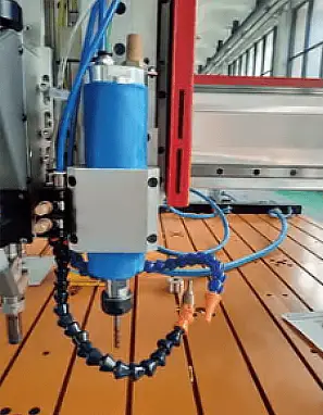
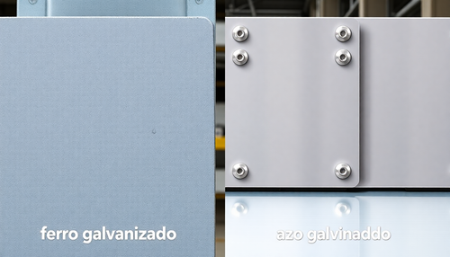
The “decoating” function is used in the processing of galvanized sheets. Due to the material difference between the zinc surface layer and the inner plate, if the surface is not treated, problems such as burning and false welding will occur during the nailing process, affecting the processing quality and increasing the post-processing workload .
Our independently developed “coating removal” technology can avoid these problems.
When users activate the “coating removal” function in the program, the device will automatically use the cutter head to clean the surface coating, and the “coating removal” depth can be adjusted as needed to ensure that the device is applicable to any coating thickness.
This not only makes the processing area more aesthetically pleasing and ensures processing quality, but also significantly improves processing efficiency and reduces waste of labor and materials in post-processing.
The spatter prevention function connects the gun head to the high-efficiency welding spatter prevention fluid to prevent welding spatter oxides from sticking to the original material due to high temperature, reducing false welding and lost welding and protecting workers against injuries from welding slag.
Before welding, spray anti-spatter fluid on both sides of the weld seam. The fallen slag reduces significantly, and any slag remaining on the surface can be wiped off with a cloth, leaving no trace and preventing rust, without affecting the subsequent painting of the surface.
The blowing function can blow out the iron filings after processing the cutter gun head, avoiding blowing with your mouth or cleaning your hands, which may cause the iron filings to fly into your eyes or cut your fingers.
Conclusion
The automatic CNC pin welding machine has excellent features and clear advantages, and is widely used in the production of thin plate pin welding in areas such as electrical, electronics, boilers, power construction, decoration and household appliances, elevators, automotive industry, shipbuilding industry and aerospace industry.