The milling machine is a widely used machine tool, and its main movement is the rotational movement of the cutter, while the feed movement is generally the movement of the workpiece driven by the worktable.
There are many types of milling machines, including:
- Horizontal milling machines
- Vertical milling machines
- Gantry milling machines
- Tool Milling Machines
- Keyway milling machines

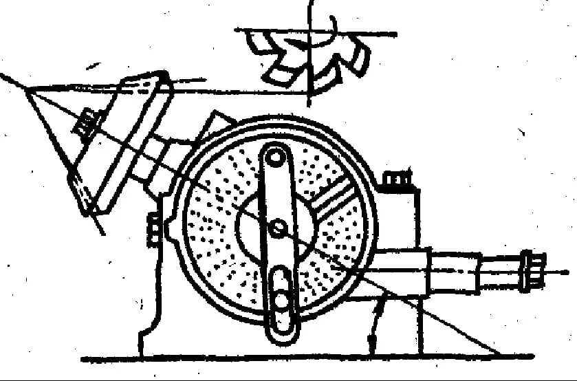
Main components of a horizontal milling machine
(1) Bed
The base is the main body of the machine tool, with most of the components installed on it.
The spindle, spindle speed change mechanism and other parts are installed inside the bed.
The front wall of the bed has vertical dovetail guide rails for the up and down movement of the table, while the top of the bed has horizontal dovetail guide rails for the forward and backward movement of the beam transversal.
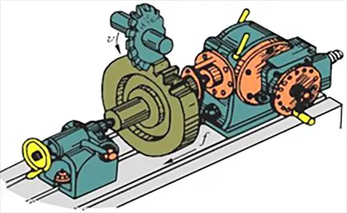
At the rear of the bed, there is a main motor that drives the spindle through a speed change mechanism installed inside the bed.
Spindle speed is changed using a handle and dial scale, both located on the upper left side of the bed. It is necessary to stop when changing gears.
An electrical cabinet is located on the lower left side of the bed.
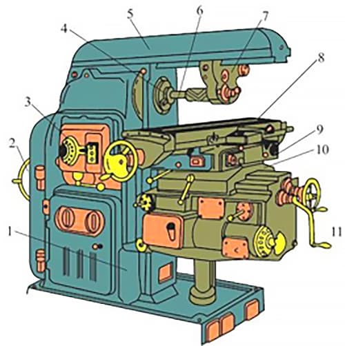
- Bed
- Main drive motor
- Spindle speed change mechanism
- Spindle
- Platter
- Cutter arbor
- Overhead crane
- Longitudinal work table
- Rotative desk
- Cross work table
- Lifting platform
(2) Platter
The length of the cross beam can be adjusted by moving it forward or backward with the help of gears and racks, and it can be fixed using two sets of eccentric bolts.
A bracket is installed on the cross beam to support the protruding end of the cutter bar, which increases the rigidity of the cutter bar.
(3) Table
It is the support of the work table, with the longitudinal table, the transverse table and the rotary table of the milling machine mounted on it.
The feed motor and feed speed change mechanism are independent components installed on the left front side of the table, which control the movement of the table, longitudinal work table and transverse work table.
Changing the feed rate is controlled by a mushroom-shaped lever, which allows for speed changes while driving.
The table can move along the vertical dovetail rails of the bed. Below the table is a vertical lead screw, which not only raises and lowers the table, but also supports it.
Manipulation of the cross work table and lift table is controlled by the handles on the left side of the lift table.
There are two interconnected handles that have five positions: up, down, forward, backward and stop. The five positions are interconnected.
(4) Longitudinal work table
It is used to install parts or accessories and moves longitudinally with the part during forward motion.
There are three T-slots on the top of the longitudinal work table for installing fixing screws (T-bolts). One of these three T-slots has higher accuracy than the other two. There is also a small T-slot on the front of the worktable for installing travel limit blocks.
The width of the longitudinal work table is the main specification that indicates the size of the milling machine.
(5) Cross work table
The transverse working table is located below the longitudinal working table and is used to make the longitudinal working table move back and forth.
With the longitudinal worktable, transverse worktable and lifting table, the workpiece can be moved in three coordinated directions perpendicular to each other to meet machining requirements.
There is a rotary table between the longitudinal working table and the transverse working table of the universal milling machine. Its sole purpose is to allow the longitudinal work table to rotate within a positive or negative angle not exceeding 45 degrees in the horizontal plane, for milling helical grooves.
The presence or absence of a rotary table is the only distinguishing feature between universal horizontal milling machines and ordinary horizontal milling machines.
(6) Axis
The spindle is used to install cutters directly or through a cutter spindle and drives the rotation of the cutter. The spindle is a hollow shaft with a 7:24 tapered hole at the front end for installing milling cutters or milling chucks.
A long screw goes through the spindle hole on the back to hold the cutters or cutter holders in place.
The base supports the entire weight of the milling machine and retains the cutting fluid. It is the foundation of the entire milling machine and is designed to ensure that the machine is stable and rigid during operation.
In addition, there are also auxiliary devices such as crane and cutting chuck.
X6132 Universal Horizontal Lifting Table Milling Machine.
(1) Milling machine model and specifications.
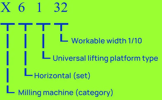
(2) Main technical parameters:
The work surface area of the table is 320mm x 1250mm, and the maximum table travel (manual) is 700mm longitudinally, 255mm transversely and 320mm vertically. The maximum table travel (automatic) is 680 mm longitudinally, 240 mm transversely and 300 mm vertically.
The maximum table rotation angle is ±45° and the distance from the spindle axis to the work table surface is 30 mm to 350 mm. The spindle speed has 18 levels ranging from 30rpm to 1500rpm.
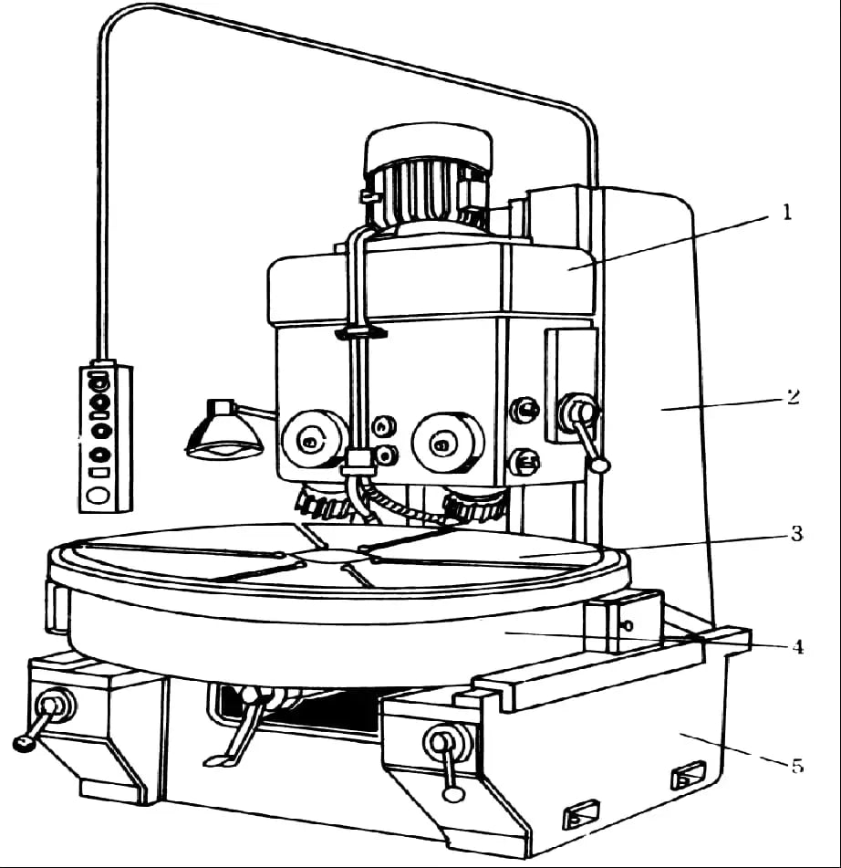
Vertical lifting table milling machine.
The vertical milling machine is similar to the horizontal milling machine in many ways. However, it differs in that it does not have an upper guide rail or cross beam in the bed.
Instead, the top front part of the machine has a vertical milling head, which is used to install the spindle and cutter.
Typically, a rotary table is placed between the base and the vertical milling head on a vertical milling machine, which allows the spindle to tilt at a certain angle to mill inclined surfaces. The vertical milling machine can also be used to make holes.
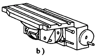
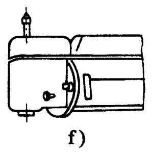
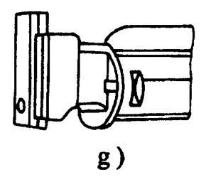
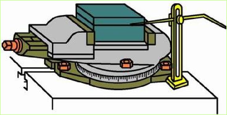
Milling machine accessories
b) Tilt of the work table
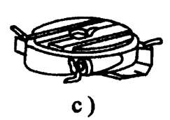
c) Rotating work table.
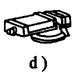
d) Simple lathe
e) Dividing head.
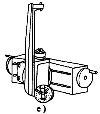
f) Vertical milling head.
g) Insert milling tool
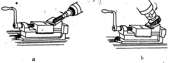
1. Flat nose pliers
Also known as a machine vise, these pliers are commonly used to hold small to medium-sized workpieces that are rectangular or cylindrical in shape. Rotary dial pliers are called flat nose rotary pliers, which can be used to adjust angles.
This method is commonly used to install small, regularly shaped parts.
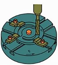
2. Rotating Table
This tool is used to clamp parts that require machining curved surfaces. It is particularly useful for milling relatively uniform inner and outer circular arc surfaces.
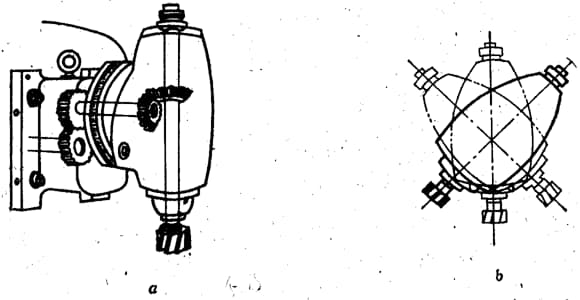
3. Universal Milling Cutter
Expand the processing range of horizontal milling machines. Installing a universal milling head on a horizontal milling machine not only allows multiple vertical milling operations, but also allows the mill axis to be adjusted to any angle based on milling needs.
However, due to the complicated installation of the universal milling head and the significant reduction in working space after installation, its use is limited.
4. Universal dividing head
The application of a dividing head:
As one of the important accessories, the dividing head is commonly used to install workpieces for milling inclined surfaces, perform indexing operations, and use various indexing methods (such as simple indexing, compound indexing and differential indexing) for various indexing tasks.
Furthermore, the dividing head can be used to install the workpiece at the required angle to facilitate cutting processing (such as milling inclined surfaces). When milling helical channels, the dividing head can be connected to the milling machine's longitudinal table screw with a “gear gear” to provide the workpiece in the dividing head with spiral movement while the table moves.
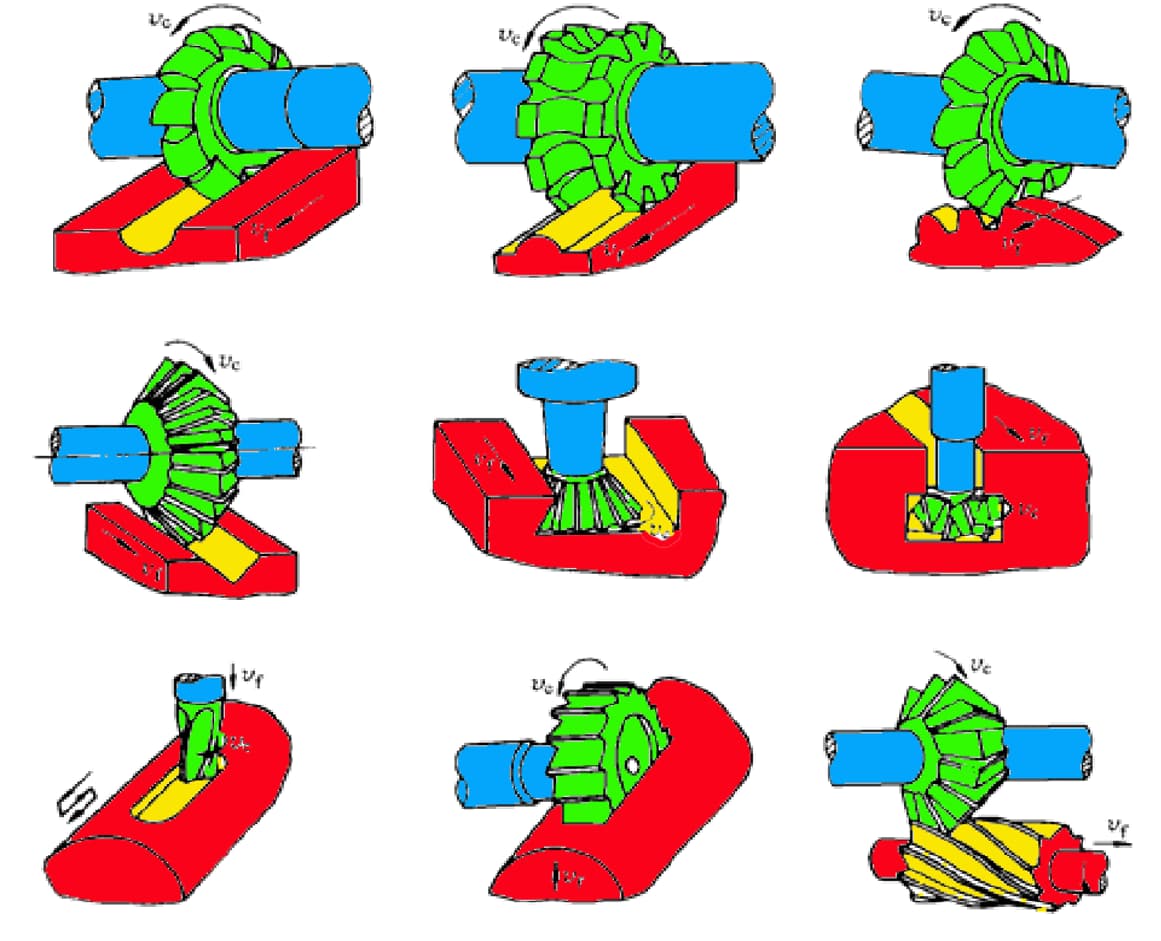
Milling cutter
The milling cutter is a multi-toothed tool generally produced in specialized factories due to its complex structure. Due to the large number of teeth that participate in cutting at the same time and the ability to use high cutting speeds, it presents greater productivity.
There are many types of cutters and several ways to classify them, including by use, combination method, tooth profile shape, etc. Here we will mainly introduce the classification by usage.
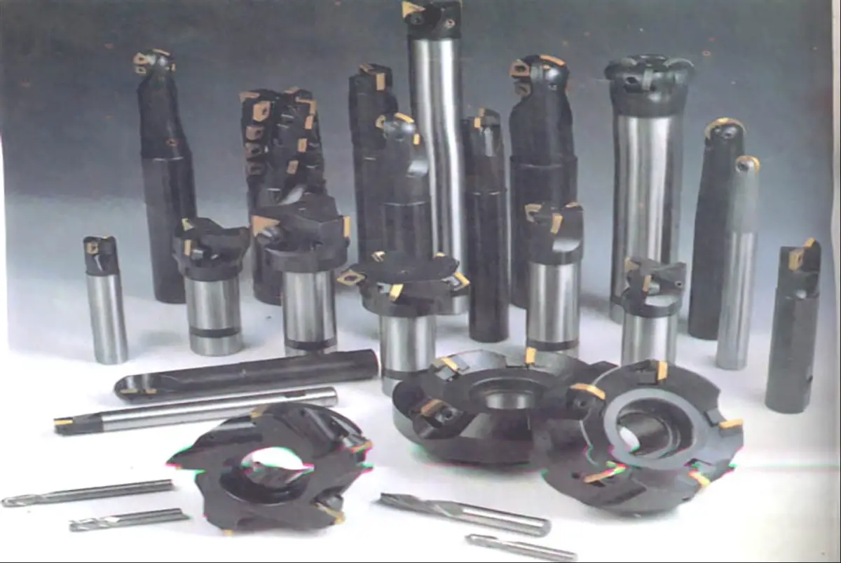
Types of cutters
Classification of milling cutters by use:
- Cylindrical milling cutter
- End mill
- Disc cutter
- Saw Blade Milling Cutter
- Face mill
- Keyway cutter
- Angle cutter
- shape milling cutter
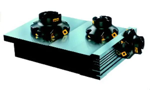
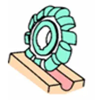
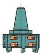
Face milling cutter
- The. Used for machining flat surfaces on vertical milling machines
- B. Each tooth of the face mill is similar to a lathe cutting tool, and the teeth are made of hard alloy.
- w. The main cutting edge of the cutter is distributed at one end of the cutter.
- d. The axis is perpendicular to the surface being machined during operation.
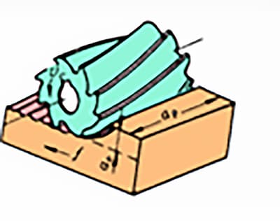
Cylindrical milling cutter
The cylindrical milling cutter is generally made of high-speed steel as a whole. The spiral cutting edge is distributed on the cylinder surface without secondary cutting edge. The spiral teeth gradually cut in and out of the workpiece during the cutting process, so the cutting process is relatively stable.
It is mainly used for machining narrow and long surfaces with a width less than the length of the cutter on horizontal milling machines.
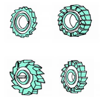
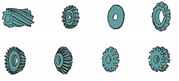
Disc cutter
The disc mill includes:
- Groove cutter
- Double end mill
- Three-edge milling cutter
Groove cutter. It has teeth only on the surface of the cylinder and can only be used to machine shallow grooves.
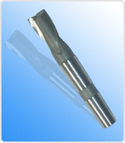
Keyway cutter
A. It is a special cutting tool for milling keys, with only two flutes.
B. Either the circumferential cutting edge or the end cutting edge can serve as the main cutting edge.
C. When in use, the cutter enters the workpiece first through the axial feed and then mills the keyway along the direction of the keyway.
D. Only the final cutting edge needs to be ground during resharpening.
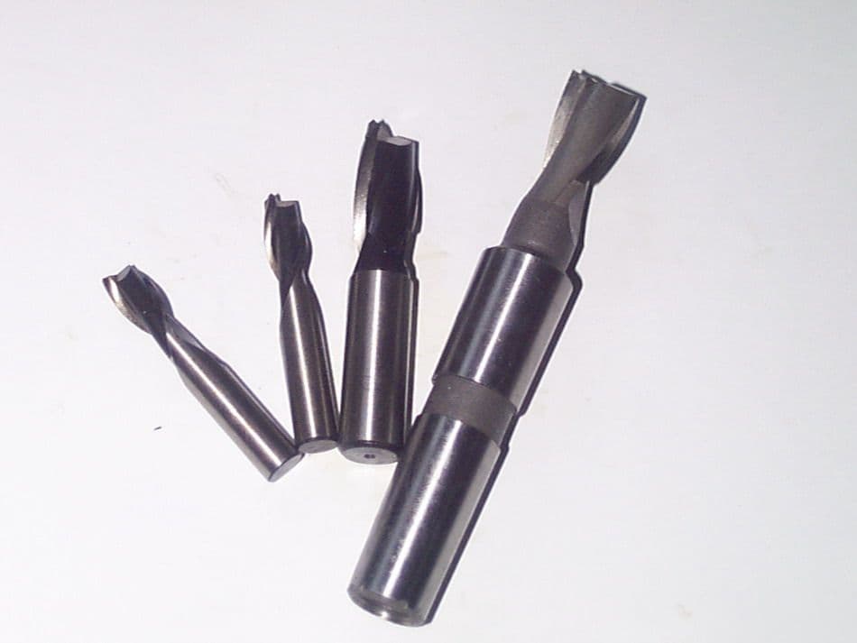
End mill
The difference between twist drills, face mills and keyway mills:
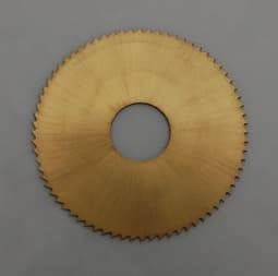
Saw Blade Milling Cutter
Saw blade cutters are mainly used for cutting or milling narrow grooves to a certain depth.
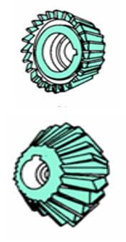
Angle cutter
Single and double angle cutters are used to mill grooves and chamfers in workpieces.
shape milling cutter
Forming cutters are used to machine contoured surfaces, and the shape of the cutter teeth is designed to match the contour shape of the surface of the part being machined.
Classification of cutters by the shape of the back of the tooth:
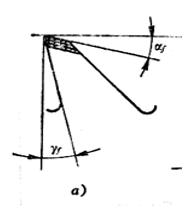
1. Pointed tooth milling cutter
The back of the pointed tooth milling cutter is mainly linear and is milled by an angle cutter. This type of cutter always has a pointed design. It can be easily crafted and sharpened, and can be resharpened along the back cutting surface after becoming dull. This type of cutter has a sharp blade.
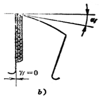
2. Milling cutter with shaped teeth.
The back of a shaped tooth milling cutter is a special curve, usually an Archimedean spiral. The back of the tooth is machined using the shaving method. After the tooth is dull, it can be ground along the front cutting surface.
The shape of the cutter teeth remains unchanged after regrinding. This type of cutter is commonly used to machine complex shapes of forming cutter cutting edges.
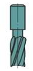
Shank milling cutter:
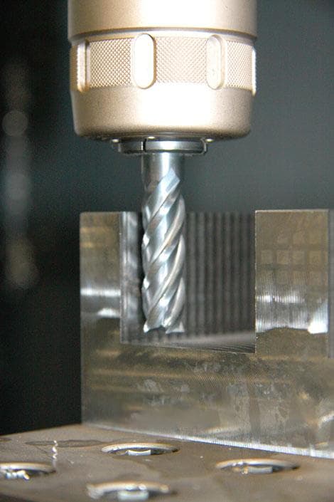
1) End mill
The cutter teeth are distributed on the end face and cylindrical surface of the cutter. It is often used to machine flat surfaces on a vertical milling machine, and can also be used to machine flat surfaces on a horizontal milling machine.
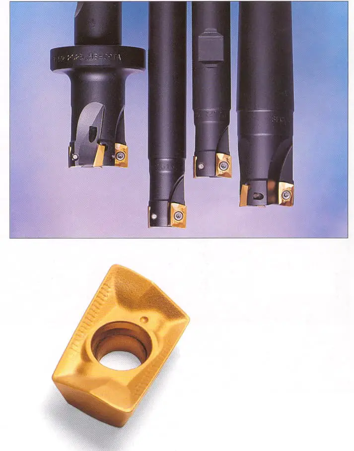
2) Face milling cutter
It is suitable for milling contour surfaces, end faces, inclined planes, grooves and stepped surfaces, etc.
3) Keyway cutter and T-slot cutter
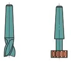
It is specifically used for machining keyways and T-slots.
4) Dovetail cutter
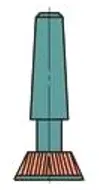
It is specifically used for milling dovetail grooves.
Milling cutter with holes :
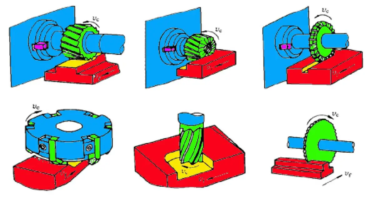
The scope of milling machining
Milling is a high productivity machining method. Normally, the milling accuracy can reach IT9 to IT8, and the surface roughness Ra value can reach 6.3 to 1.6μm.
Milling has a wide range of processing capabilities, including milling flat surfaces, steps, grooves, forming surfaces, helical grooves, gear tooth surfaces, cutting and engraving lines. Additionally, hole machining tools such as drills, reamers and boring bars can be installed on the milling machine to process holes in workpieces.
Milling methods
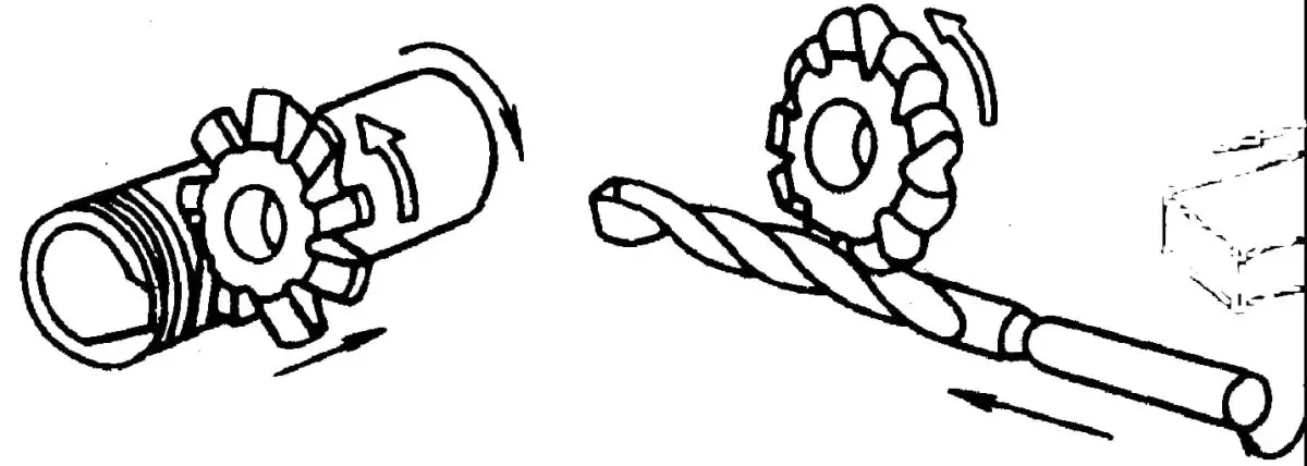
Conventional milling and up milling
Definition: When the direction of rotation of the cutter is opposite to the direction of progress of the part, it is called conventional milling. When they are in the same direction, this is called climb milling.
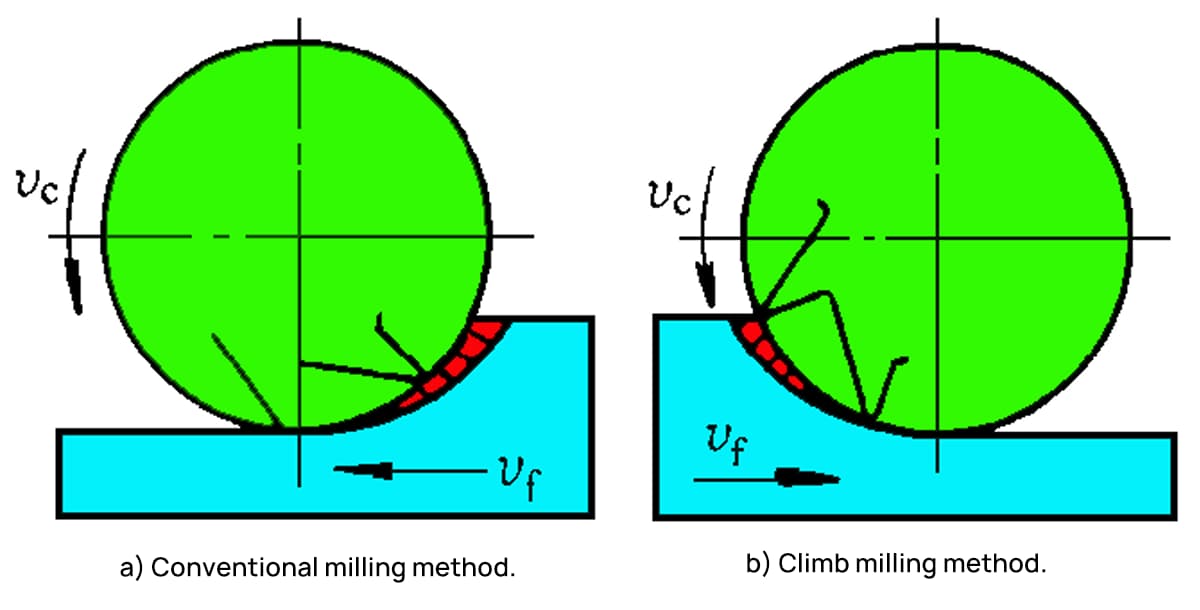
Characteristics:
1. In conventional milling, the cutting thickness gradually increases from zero.
Due to the influence of the blunt edge radius, the face angle is negative at the beginning of the cut. The teeth are compressed and slide on the surface of the part, resulting in severe surface hardening and increased tooth wear.
On the other hand, in down milling, the cutting thickness starts at the maximum. Tool wear is lower and durability is high.
2. In climb milling, the cutting force in the feed direction is the same as that in the workpiece.
Due to the clearance between the screw and nut of the work table, when the feed force gradually increases, the cutting force will pull the work table and cause deformation, resulting in uneven feed.
In severe cases, it can cause the cutter to break.
However, in conventional milling, due to the action of feed force, the transmission surface between the screw and the nut is always in close contact, so the milling process is relatively stable.
3. In conventional milling, the vertical cutting force is opposite to the clamping force and the weight of the workpiece, which tends to lift the workpiece off the work table, exacerbating vibration and affecting the workpiece's clamping and surface roughness.
On the other hand, in down milling, the vertical cutting force is downward, resulting in reliable clamping.
Features of down milling:
- The chips start out thick and the cutter is more durable;
- The milling force presses the workpiece, resulting in stable and smaller vibration;
- The machine tool has deformation, but is susceptible to surface polishing;
- Compared to conventional milling, it is suitable for precision machining.
Features of conventional milling:
- Chip thickness increases from fine to coarse;
- Initial cutting causes tooth compression, slippage and increased tool wear;
- The milling force eliminates the displacement of the machine table;
- Conventional milling is used to avoid surface polishing and deformation.
Symmetrical milling and asymmetric milling
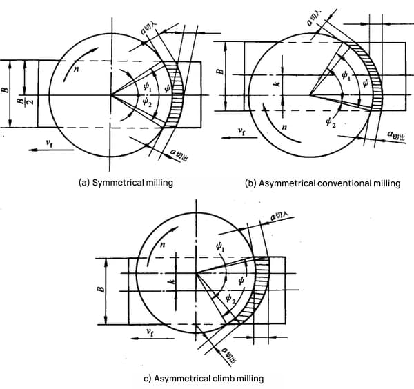
1. Symmetrical milling:
The cutter axis is located in the middle of the machined surface during milling, which is called symmetrical milling. Symmetrical milling generally has a larger average cutting thickness and is commonly used for parts with wide machining surfaces and hardened steel.
2. Asymmetrical milling:
Milling with the cutter axis located on one side of the machined surface is called asymmetric milling. Depending on the axis position of the cutter, it can be divided into conventional asymmetric milling and asymmetric up milling.