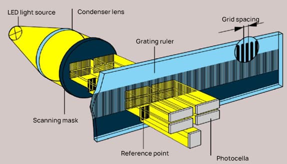
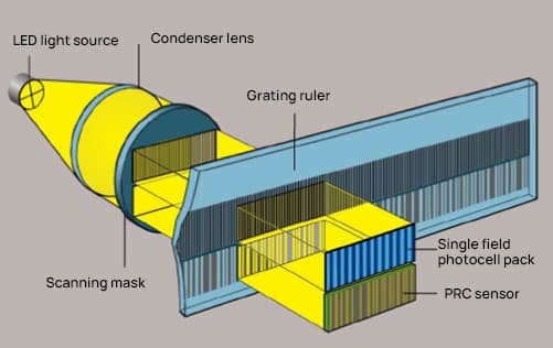
Grid Structure and Working Principle.
1. Grid Structure
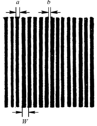
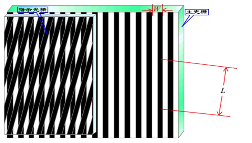
Grid – many small stripes (etched lines) of equal distance and alternating brightness and darkness are evenly etched onto a coated glass surface.
a – is the width of the grid lines (not transparent)
b – is the width of the space between the grid lines (transparent)
a+b=W grid step (also known as grid constant)
Typically a=b=W/2, but can also be written as a:b=1.1:0.9.
Commonly used grids are engraved with 10, 25, 50, 100 or 250 lines per millimeter.
2. Grid measurement principle
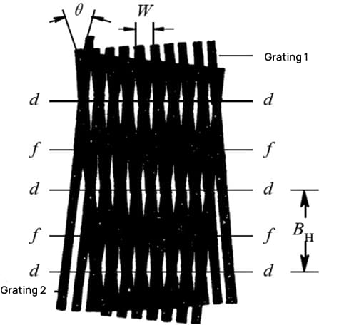
Moiré fringes – When two grids of equal pitch (Grid 1 and Grid 2) are superimposed face to face, leaving a small gap in the middle, and the small grid angle θ is formed between the two grid lines, alternating bright and dark stripes appear in the direction close to the vertical line of the grid.
In line dd, the two grid lines overlap, and the transparent area is the largest, forming the bright band of the strip – which consists of a series of diamond patterns.
In line ff, the two grid lines are offset, forming the dark band of the stripe – consisting of some black criss-cross line patterns.
Moiré fringe displacement measurement has the following three characteristics:
(1) Displacement amplification effect
BH Sash Width – When the grid moves forward or backward by one swath step, the moiré fringes move forward or backward by one swath width.
The relationship between BH and θ:
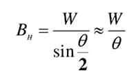
As θ decreases, BH increases. Therefore, W is amplified by 1/θ. For example, when θ=0.1°, 1/θ=573, it means that BH is 573 times the grating pitch W. This means that the grating has a displacement amplification effect, thus increasing the measurement sensitivity.
(2) Direction of the Moire Fringe Movement
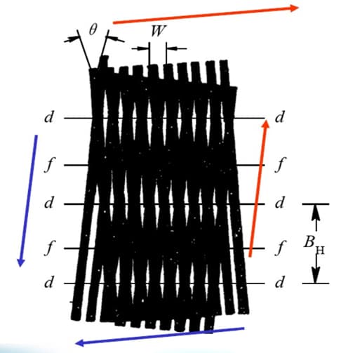
When Grid 1 moves to the right along the cutting line in the vertical direction, the Moiré fringes move upward along the grid lines of Grid 2. Conversely, when Grid 1 moves to the left, the Moiré fringes move downward along the grid lines of Grid 2. Therefore, the direction of motion of Grid 1 can be identified as the direction of motion of the Moiré fringe →.
(3) The average effect of error
Moiré fringes are formed by the large number of lines engraved in a grid and have an effect opposite to the engraved error of the lines. This effect can significantly reduce the influence of short-term errors.
Composition of grid sensors
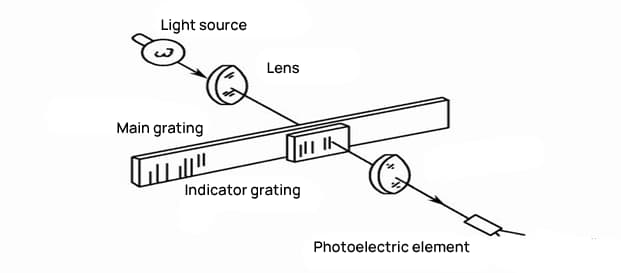
Grid read head: Utilizes the principle of grids to convert the input quantity (displacement) into a corresponding electrical signal.
Components: Ruler grid, indicator grid, optical path system, photoelectric elements, etc.
Digital Grid Display: To discern direction of travel, increase measurement accuracy, and enable digital display, the output signal from the grid read head must be converted to a digital signal.
Components: Modeling amplification circuit, subdivision circuit, directional discrimination circuit and digital display circuit, etc.
Closed Grid Ruler Structure
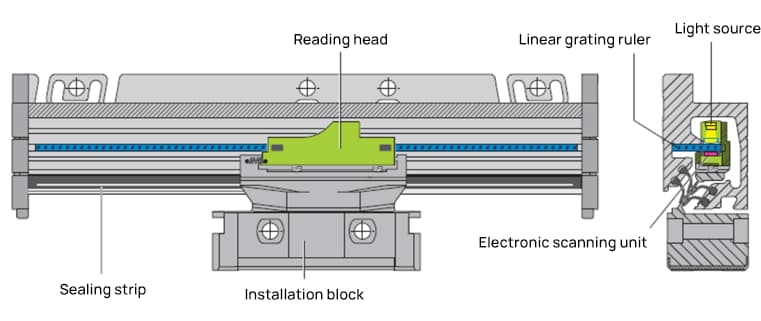
The grid ruler consists of a fixed scale body and a movable reading head.
The fixed scale body is an aluminum housing designed to protect the ruler, scanning unit and internal guide rails from damage caused by chips, dust or splashing water.
The movable reading head consists of a scanning unit, a precision connector and an installation block. The precision connector connects the scanning unit to the installation block, which compensates for small mechanical errors in the guide rails.
Function and advantages of grid ruler
The linear grid ruler is used to measure the position of linear axis movement. Because it directly measures the mechanical position, it can accurately reflect the actual position of the machine tool.
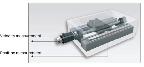
When using the linear grid ruler to measure the position of the slide, the position control circuit includes all feeding mechanisms. This is the closed loop control mode. The mechanical movement error is detected by the linear grid ruler on the sliding plate and corrected by the control system circuit.
Therefore, it can eliminate potential errors from multiple sources:
- Positioning error caused by the temperature characteristics of the ball screw and guide rails
- Ball screw reverse error
- Characteristic motion error caused by ball screw pitch error
Applications of grid rulers
Processing equipment: lathes, milling machines, boring machines, grinding machines, drilling machines, EDM machines, wire cutting, machining centers, etc.
Measuring instruments: projectors, image measuring instruments, tool microscopes, etc.
It can also compensate for errors in tool movement on CNC machine tools
Equipped with PLC for measuring displacement in various automated mechanisms.
Measuring principle of grid ruler
Incremental Grid Ruler
The measuring principle of the incremental grating ruler is to modulate light through two mutually moving gratings in Moiré fringes. Counting and subdividing the Moiré fringes, the displacement variation is obtained. Absolute position is determined by defining one or more reference points on the scale grid.
Characteristics:
The grid ruler has advantages such as simple structure, long mechanical life, high reliability, strong anti-interference ability, long transmission distance, high precision and low cost.
However, incremental grid sensors also have shortcomings. Incremental grid rulers can only generate the relative position of the axis rotation.
The reference point must be set whenever power is turned off or restarted and there is any subdivision error in the signal processing method.
Absolute grid ruler
The measurement principle of the absolute grid ruler is to directly encode the absolute position data in the form of codes on the grid, through flickering grid lines in different widths and spacings on the grid ruler.
Subsequent electronic equipment can obtain position information while the grid ruler is turned on.
Benefits:
Current position information can be obtained directly after startup without the need for a “zero” operation, simplifying control system design. Absolute position calculation is completed in the read head without the need for subsequent subdivision circuits. The use of bidirectional serial communication technology ensures reliable communication.
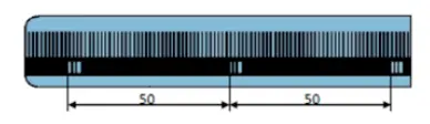
Types of landmarks
The absolute position of the grid ruler is determined using reference markers (zero positions).
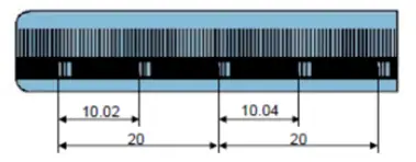
To shorten the distance to return to the zero position, Heidenhain has designed distance-coded reference markers within the measuring length.
The absolute position of the grid ruler can be determined each time two reference markers (with a distance determined by mathematical algorithms) are passed.
Encoders with distance-coded reference points have the letter “C” after the model number (for example, LS 487C).
Unique reference point
Equidistant reference points.
Distance coded reference point/type C.
| Signal cycle | nominal increment number | maximum travel distance | |
| IF | 4μm | 5,000 | 20mm |
| LS | 20μm | 1000 | 20mm |
| LB | 40μm | 2000 | 80mm |
Unreferenced absolute linear scale
Classification of Linear Scale Signs
Absolute signal: Endat, Fanuc series, Siemens, Mitsubishi, Panasonic, etc.
Incremental signal: sine wave signal (1 Vpp signal), square wave signal (TTL signal).
Technical Specifications of Linear Scales
1. Grid step:
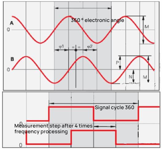
The linear scale outputs electrical signals, and the grid pitch refers to the physical grid lines on the linear scale. Each time the linear scale moves a distance equal to the grid pitch, the output electrical signal changes one cycle.
Example: When the grid pitch is 20um, if the linear scale moves a distance of 20um, the linear scale will produce a sine wave with 360° phase shift and 90° biphasic difference.
2. Signal Cycle:
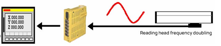
With the development of measurement technology, it is now possible to use frequency multiplication circuits in the linear scale read head to multiply the sine wave generated by each grid line signal.
Therefore, the linear scale signal output cycle can be refined. The signal after being multiplied by the read head is much denser than the original gridline signal, and the length of the densified signal is called the signal cycle.
If the read head does not have frequency multiplication capability, the grid pitch will be equal to the signal cycle.
3. Frequency multiplication:
Frequency multiplication can be understood as the densification of the original signal. Frequency multiplication can shorten the period of a sine wave, shorten the measured distance corresponding to each period, and improve measurement accuracy.
Common frequency multiplication methods include: read head frequency multiplication, post-multiplication instruments (supplied by linear scale manufacturers, similar to preamplifiers, used for signal amplification and frequency multiplication), frequency of CNC systems, etc.
4. Measurement step:
Sine wave signals that have undergone frequency multiplication are used to measure position. Due to limitations in the manufacturing process, error level and processing capacity of the linear scale position recording circuit, it is impossible to infinitely multiply the original grid pitch signal.
Therefore, manufacturers of linear scales have a recommended measurement step for each type of linear scale. This value refers to the minimum measured distance that the linear scale can tolerate. Within this range of measuring steps, the nominal measuring accuracy of the linear scale can be achieved.
Compared to CNC systems, this measurement step is generally the minimum instruction unit of the system. Likewise, this technical specification also specifies the measurement accuracy (resolution) of the linear scale.
5. Resolution:
Measurement accuracy refers to the minimum length change that the linear scale can read and produce, such as 5um, 1um, 0.5um, 0.1um.
6. Measurement Accuracy:
Measurement accuracy refers to the accuracy of the signal data output by the linear scale relative to the actual length being measured.
Position error within the entire measuring range: If the maximum value of position error established on the basis of the average value within any 1 m long measuring range is within ±a, then ±a one is the level of precision.
On closed linear scales, this data reflects the accuracy of the linear scale, including the reading head, i.e. the accuracy of the system. (Heidenhain: ±0.1, ±0.2, ±0.5, ±1, ±2, ±3, ±5, ±10, ±15um)
Position error within a single signal cycle:
The position deviation within a single signal cycle is determined by the grid quality, scan quality, and linear scale signal cycle. The position error within a single signal cycle is generally in the range of ±2% to ±0.5% of the signal cycle.
The shorter the signal cycle, the smaller the error within a single signal cycle. This is very important for positioning accuracy during slow motion and spindle movement and speed control during spindle movement, which determines the surface quality and quality of processed parts.
| The signal cycle of the sweep signal | The maximum interpolation error within a single signal cycle | |
| Florida | 4μm | 0.08μm |
| LC181 | 16μm | 0.3μm |
| LC481 | 20μm | 0.4μm |
| LS | 20μm | 04μm |
| LB | 40μm | 0.8μm |
Factors to Consider When Selecting a Linear Scale
- Measuring length.
- Signal interface: 1Vpp, TTL, HTL, absolute linear scale.
- Grid step.
- Measuring speed.
- Level of precision and resolution.
- Space for installation position.
- Method of establishing reference points.