
Introduction to Sheet Metal Construction
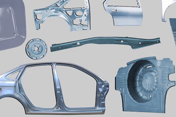
Take a look and you will find that there are plenty of sheet metal products available. Whether consumer products such as beverage cans, kitchen utensils, files or industrial products such as car bodies, structures and exhaust systems. Sheet metal is a valuable commodity for industry and small-scale production. Therefore, this article is dedicated to the basics of sheet metal design and some useful tips for sheet metal designers. Many industries are adopting the concept of Design For Manufacturability or better known as DFM. In the sheet metal design industry, DFM helps prevent technical errors in the design process to improve manufacturing lead times based on the sheet thickness table and previous calculations. Therefore, sheet metal design for manufacturability is also an important topic covered in this article.
What is sheet metal?
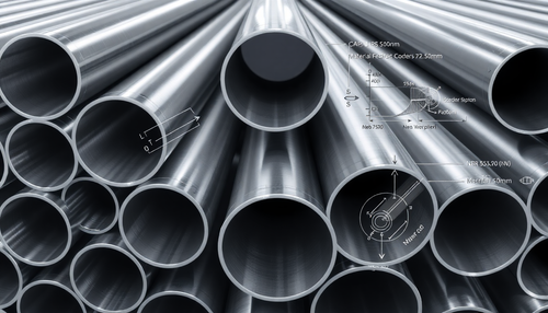
Before we delve into the technical details of sheet metal construction, we must first understand what sheet metal is. Sheet metal is a metal such as aluminum, brass, titanium, nickel, tin, and copper that is processed into thin, flat pieces such as sheets, sheets, and plates.
Because they are light, thin, resistant and elastic, they are widely used in industry for coating and covering purposes.
Basic Sheet Metal Processing Operations
Sheet metal fabrication is the process of forming and cutting sheets, coils, and strips to create product components and parts. There are several methods for constructing sheet metal, some of which are explained below.
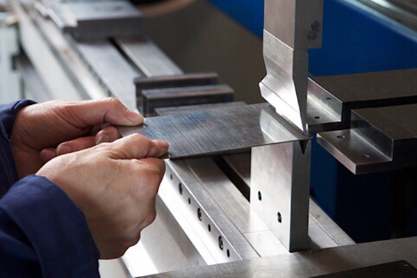
1. Push-up
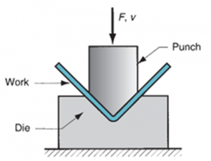
Bending is bending metal sheets around a straight axis, applying a force to a specific area. The workpiece is placed on a die block and a punch is pressed to give the desired shape to the sheet metal. Different industries use different tools to bend metal, but the most common tools are press brakes or press brakes.
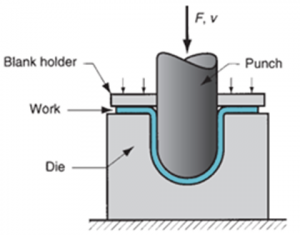
2. Drawing
Another sheet metal drawing process is wire drawing, also known as cup drawing or deep drawing. It involves stretching metal sheets to form a hollow or concave shape. A fixture holds the part in a die while a U-shaped punch punches the sheet metal part. The attached figure illustrates the process:
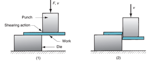
3. Scissors
Unlike the operations described above, shearing is a sheet metal processing process in which the part is cut by applying force to the punch, rather than a sheet metal forming process.
As shown in the figure, the metal part that is first placed in the die experiences a vertical force on the punch, which creates a shearing effect and cuts the part.
4. Multiple processes
There are several other sheet metal construction methods that may involve using dies and punches to bend the metal. These procedures include
DFM Guidelines for Sheet Metal Design
Differences between computer-aided designs and real products are inevitable. However, following DFM guidelines can reduce these errors. DFM or Design for Manufacturability is based on the concept of designing parts, components, pieces or products to be easy to manufacture and more economical. The focus is on reducing general production costs by reducing lead time.
Research shows that manufacturers spend about 40% of their time fixing defects, 24% of which are manufacturing defects. Therefore, industries need to resolve these flaws. Adhering to DFM guidelines can significantly reduce design errors.
DFM focuses on simplifying part design to ensure easy manufacturing and repeatability. It proposes the standardization of parts to reduce the number of parts and produce quality products with a good cost-benefit ratio.
Some basic factors for sheet metal design
Sheet metal design for manufacturability focuses on points that are critical throughout the design process. The following guidelines will help improve the design:
You should avoid making small holes in the metal piece, as this requires small holes that may break during the process. Therefore, the holes must have a diameter equal to or greater than the thickness of the part.
A depression in sheet metal structures is called bend relief to allow the bending process to occur smoothly during the sheet metal design process. Helps prevent breakage during the bending process.
It is recommended that the distance between holes and a bend is 1.5 times the sheet thickness plus the bend radius.
A minimum bending radius for sheets must be maintained. This minimum bend radius depends on the tools used to bend the metal. The more flexible the metal, the easier it is to obtain a small radius.
For sheet metal construction, the minimum flange width should ideally be four times the sheet thickness. This factor is crucial when it comes to the aesthetics and cleanliness of your design.
DFM Tips for Sheet Metal Design
Listed here are some sheet metal design tips to craft your design.
1. Larger hole diameters are required in relation to the sheet thickness.
2. The distance between two holes is the most important. It is recommended that this distance is twice the thickness of the sheet. This factor will help you avoid deformation of the metal in the drilled holes.
3. If the drilled holes are very close to the outer edge of the sheet, it is recommended to leave a minimum distance of the sheet thickness between the hole and the edge.
4. There should be at least 1.5 times the distance of the material thickness between the bend and the holes.
Advantages of DFM
DFM offers manufacturers a way to improve the quality of their products while reducing production costs. It offers an endless list of benefits, some of which are listed below:
Mistakes to Avoid When Designing Sheet Metal Parts
There are certain common problems encountered in sheet metal construction. Below are some of the problems that need to be avoided when designing the sheet metal part:
1. Avoid using 3D models without curves
2. Hold the perfectly vertical and sharp corners of the sheet
3. Avoid placing features close to fold lines
4. Research thoroughly before choosing a flat pattern for your designed sheet metal parts
5. Avoid choosing the wrong type of sheet metal processing to design a product
6. The CAD design file must contain detailed specifications depending on the sheet thickness table
7. Keep an eye on welding requirements and make sure you don't achieve them unrealistically
8. Always consider U-channel resistance when selecting material
Sheet Metal Prototyping
Sheet metal prototyping involves modeling a sample of a metal product to test a concept. It helps companies test an idea before starting mass production. Unlike traditional prototyping, sheet metal prototypes are designed in less time.
Different companies use different methods to produce sheet metal prototypes. Some of them are listed below:
University Degree
Sheet metal has an undeniable importance in our lives. They have a wide range of applications, from the home appliance industry to the automotive industry and from the robotics industry to consumer goods. Therefore, it is important to understand the fundamentals of sheet metal design and the DFM sheet metal design guidelines considered in the manufacturing process.