Application of press in automatic stamping production line
Automatic Stamping Production Process
In traditional stamping production lines, material handling between the front and rear equipment is performed manually. With the increasing pace of production, manual collection and unloading not only cannot keep up, but also poses potential safety risks.
Personnel tend to focus on speed, neglecting the dangers posed by moving equipment, leading to frequent accidents involving equipment pressing on hands and causing injuries. To mitigate these risks and improve efficiency, an automated robotic production line was developed.
Automated production involves using equipment instead of manual labor to transport sheets between front and back presses. This not only eliminates the risk of injuries, but also increases production efficiency by around 35%.
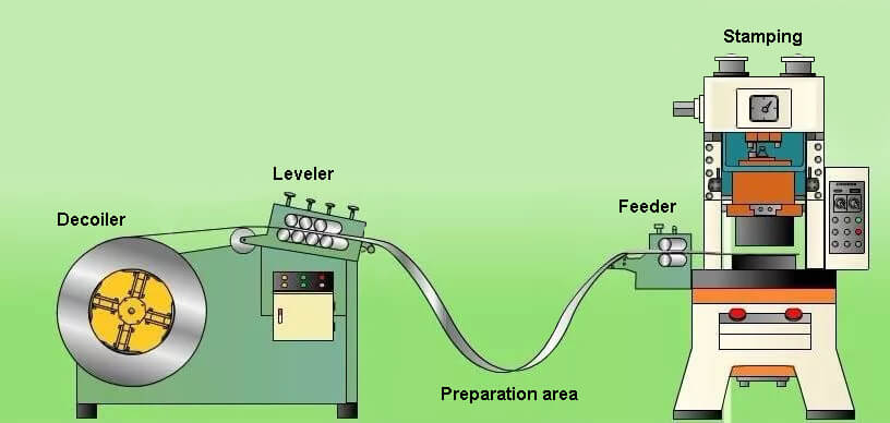
After 2005, automated production technology for stamping parts in domestic automobile manufacturing saw significant growth, marking the beginning of an era of automated stamping production. Figure 1 shows a schematic diagram of a stamping automation production line.
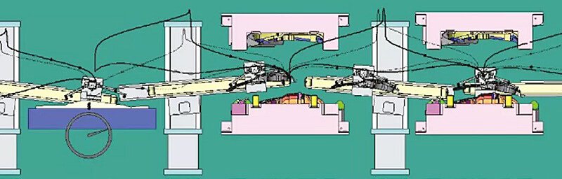
Figure 1 Schematic diagram of automatic stamping production line
Main parameters of the press production process
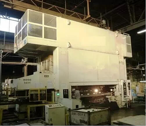
Currently, the most used presses are closed mechanical presses, which can be used for various cold stamping processes, such as stamping, forming, bending, correction and shallow drawing of thin sheet metal parts. Press process parameters are crucial as they not only affect product quality, but also have a significant impact on efficiency, cost and safety.
The following section provides a brief overview of the important parameters and accuracy of some presses:
Press basics
The press foundation must support its weight and withstand the vibrational forces generated when the press is started, and transfer these forces to the ground beneath the foundation. The foundation must be able to safely withstand 0.15 MPa. The strength of the foundation is designed and constructed by the civil engineering department based on the local soil quality. The concrete foundation must be poured in a continuous, uninterrupted operation.
After filling the foundation with concrete, the surface must be smoothed once and then smoothed again with a shovel or sandpaper. To protect against oil, the bottom surface of the foundation must be coated with acid-resistant cement. The basic drawing provides the internal dimensions of the foundation, which represents the minimum space required to install the press.
Resistance indicators such as the brand of cement, the arrangement of reinforcing bars, the size of the foundation support area and the thickness of the foundation must not be changed. The basic bearing capacity must be greater than 1.95 MPa.
Post-sync guide
Indication: It connects the beam gearbox and the slider, transmitting the decelerated movement of the gearbox to the slider to achieve the vertical movement of the slider.
There are generally single point, double point and four point types, that is, one guide post, two guide posts or four guide posts.
Post-sync guide:
It refers to the synchronization accuracy of the two- or four-point pressure guide columns in their upward and downward movement. This parameter is normally established before the printer leaves the factory. The timing accuracy of the guide post should be kept within 0.5mm. Excessive misalignment will result in significant tensile stress on the sliding force, affecting the quality of the product formed at bottom dead center.
Mold mounting height
Mounting height refers to the distance between the bottom surface of the slider and the top surface of the table. There are maximum and minimum limits for mounting height. When designing the die, the possibility of installing and using the mold after grinding must be considered. The closed height of the mold must not reach the maximum or minimum limit values for the height of the pressing mold.
Figure 2 shows a schematic diagram of the press mounting height.
Nominal strength of the press
The rated force refers to the maximum punching capacity that the press can safely handle within its structure. In practice, factors such as material thickness and strength deviation, mold lubrication and wear must be taken into consideration to ensure an adequate margin for stamping capacity.
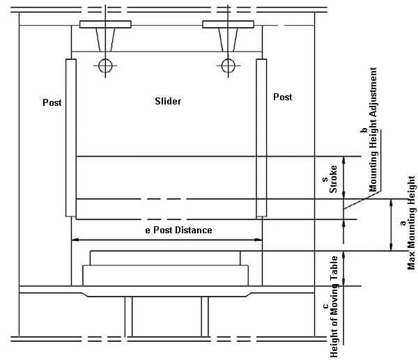
Figure 2 Schematic diagram of press mounting height
When performing an impact load operation such as blanking, it is recommended to limit the working pressure to 80% or less of the rated force. Exceeding this limit may result in significant vibration and damage to the connection between the slider and transmission, affecting the normal life of the press. Figure 3 shows the nominal load vs. load curve. allowable load.
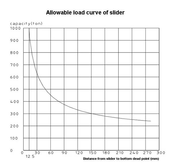
Figure 3 Permissible load curve of nominal force
compressed air pressure
Compressed air is the main source of energy to ensure the smooth operation of the press and also serves as a source of control circuit for the press's power source. The demand for compressed air pressure varies in different locations. The factory supplied compressed air pressure is based on the maximum demand value of the press. Parts with lower demand values are equipped with pressure reducing valves for regulation.
Compressed air in the stamping automation production process can be divided into two categories: product quality and action function. The product quality category is used to define the quality of the product, such as air cushion pressure. The action function category is involved in controlling press actions such as clutch pressure.
Using the press of a manufacturing company as an example, Table 1 shows the compressed air pressure values required for each functional module of the press. There are many more printer parameters than the five listed above.
The following is a brief summary and display of the company's printing parameters (Table 2) for your reference.
Table 1 Required compressed air pressure value for each functional module
| No. | Item | Supply air pressure MPa | Pressure regulating valve position | Observation | |
|---|---|---|---|---|---|
| 1 | Full air supply | ≥0.5 | |||
| two | Clutch | 0.32 | Beam Walking Platform | ||
| 3 | Balancer | 0.47 | Inside the left front post | Value calculated without mold | |
| 4 | Hydraulic protection | Air bomb | 0.29 | Internal slider | Calculated |
| 5 | Flush valve | 0.32 | Internal slider | Calculated | |
| 6 | Elastic cushion | 0.04 ~ 0.8 | Inside the left front post | ||
Table 2 Summary of press parameters
| No | Item | Value | Unit | |
|---|---|---|---|---|
| 1 | Nominal strength | 10,000 | kN | |
| two | Nominal force stroke (before bottom dead center) | 12.5 | mm | |
| 3 | Slider stroke length | 1000 | mm | |
| 4 | Number of sliding strokes (during dry running) | Continuous | 8-12 | Times/minute |
| Single maximum | 8 | |||
| Tuning | 3 | |||
| 5 | Maximum loading height | 1350 | mm | |
| 6 | Loading height adjustment | 500 | mm | |
| 7 | Rail distance | E*R | 4970 | mm |
| 8 | Slider bottom surface size | E*R | 4600 | mm |
| F*B | 2400 | mm | ||
| 9 | Work table size | E*R | 4600 | mm |
| F*B | 2400 | mm | ||
| 10 | Work table thickness | 300 | mm | |
| 11 | Mobile work table | Moving path | Move left and right | |
| Amount | two | Parts | ||
| Mobile table height | 700 | mm | ||
| Carrying weight | 50 | t | ||
| 12 | Slider | Rail type | Right angle guide | |
| Type of beat | / | |||
| hitting force | / | kN | ||
| Hitting blow | / | mm | ||
| Batter number | / | Parts | ||
| 13 | Elastic cushion | Type | Pure gas single crown | |
| Amount | 1 | Parts | ||
| Ejection force | 4500 | kN | ||
| Blank holding force | 4500 | kN | ||
| stroke | 0~300 | mm | ||
| 14 | Balancer balancing force (with air pressure of 0.62 MPa) | 200 | kN | |
| 15 | Inlet air source pressure | 0.7 | MPa | |
| 16 | Free air consumption | 1 | m³/min | |
Conclusions
The press is the main equipment in the printing production process. With the rapid growth of the automotive industry, there has been a corresponding increase in demand for high-precision equipment. The development of the stamping process went through three stages: manual production line, automated intermittent production and automated high-speed continuous production. In each iteration of the model update, production equipment plays a crucial role.
Now that we have a basic understanding of the printing press, let's move on to the topic of automatic production lines.
Types of automatic stamping production line
Automatic stamping production lines mainly include: progressive stamping, multi-station stamping, and tandem stamping .
Due to their unique features, these production lines are used to produce different automotive sheet metal parts and play a significant role in automotive automation and efficient production systems. This article compares and analyzes the characteristics of these three stamping automation production lines and provides guidance on how to select a production line based on their characteristics.
This will make it easier for companies to choose a production line that meets the specific characteristics of their parts. With the rapid growth of the automobile industry, the four major stamping industries for automobile manufacturing also flourished. To meet the increase in production, several automated production lines emerged, each with its own characteristics and suitable for different products.
This article categorizes common stamping automation production lines into progressive stamping, multi-station stamping and tandem stamping, and briefly analyzes the characteristics and selection methods of each production line to help companies choose the correct production method for the characteristics of your products.
Progressive Stamping Production Line
(1. Overview:
Automatic production line for progressive stamping is a production line that employs progressive stamping and typically consists of an unwinding feeder, a punch, a progressive die and an automatic cutting line. It automates the process of coil unwinding, strip straightening, strip lubrication, blank stamping and offline collection of finished products.
The most important component is the progressive array, which consists of multiple stations, up to more than 20 stations. Each station is connected to each other to complete different processing tasks, such as punching, cutting, flanging, shaping, trimming and so on. All these tasks are completed with a single press. Upon completion of a stroke, the feeder advances the strip of material in a fixed step, allowing multiple processes to be completed in a single reciprocating press punch.
As shown in Figure 1.
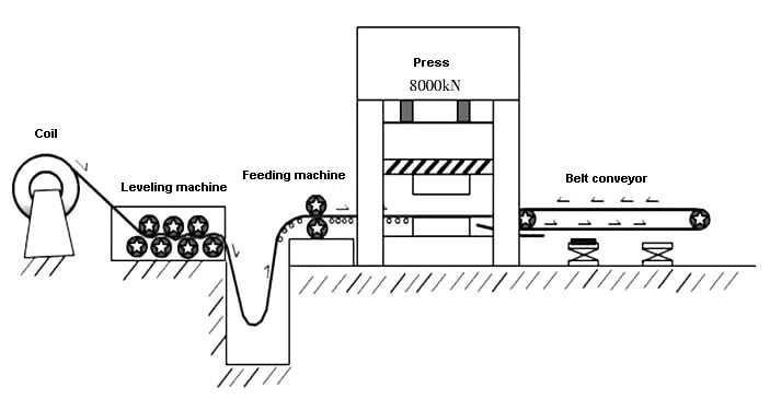
Figure 1 Simplified diagram of the automatic progressive production line
(2) Features:
The production cycle of progressive stamping automation production line is relatively high, generally up to 30 times/min.
-
High production efficiency.
The progressive die is a multi-tasking process die that can perform punching, bending, forming and drawing within a set of dies, resulting in high productivity. The progressive matrix layout process is shown in Figure 2.
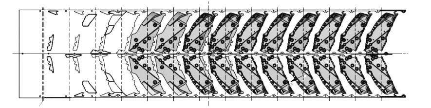
Figure 2 Progressive Matrix Layout Process
-
Easy to automate.
The progressive die production line allows automatic operation from loading, feeding, processing and unloading of parts, reducing labor costs and increasing production efficiency. Furthermore, it eliminates inconsistencies and abnormalities that may occur during manual operations. -
Can use high-speed punch production.
Depending on the product status, a high-speed punch may be considered to achieve greater production efficiency. -
Safe operation.
Progressive press equipment has safety doors to optimize the use of the material. The work area is isolated from the operator area to create a relatively enclosed work area, ensuring safety during high-speed production. This results in greater production efficiency compared to traditional series production lines. -
Save production plant area.
A machine tool constitutes the processing component of a production line and is capable of producing a product. It has a compact design, simplifies the detection of the transport of materials and semi-finished products and offers high security. -
Material usage is not high.
To ensure feed stability and meet various requirements, it is usually necessary to distribute processing tasks evenly at each stage. This may result in some of the material being sacrificed, resulting in a lower material utilization rate.
Multi-station Stamping Automation Production Line
(1) Overview:
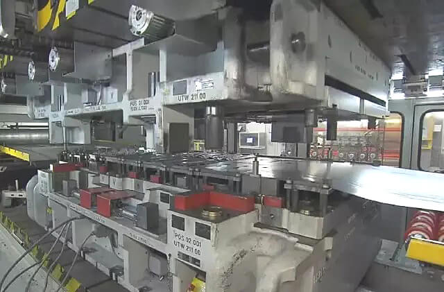
A production line with multiple independent mold stations (usually 4 to 5) located on a large tonnage press table uses a destacker or unwind feeder for loading, an automatic feed bar for transferring processed parts, and an automatic conveyor belt for collect finished products offline. As shown in Figure 3.”
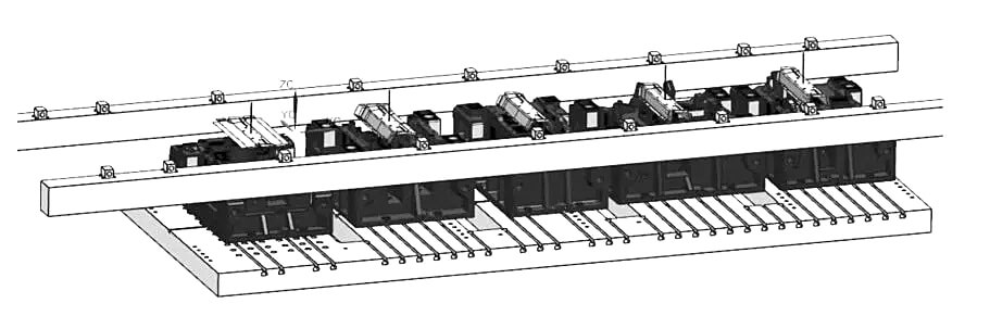
Figure 3 Multi-station stamping automation production line
(2) Features
The bottom material can be a roll material or a blank, which provides flexibility and improves the material utilization rate. The production line uses automatic rod feeding and has a lower punching rate compared to the progressive die production line, but a higher rate than the traditional tandem production line, resulting in higher production efficiency.
It can also incorporate sensors such as loading and unloading sensors, dual material detection, adhesion sensors, in-mold sensors, etc. to monitor the position and status of material and product during production, ensuring high safety.
There are strict requirements for the feeding height and stamping direction of molds at each station, and to maintain feeding stability, the states of each process must generally be consistent.
Tandem Stamping Automation Production Line
(1) Overview:
An automated production line is formed by arranging multiple presses in series. Each press table contains a pair of molds, which represent a step in the production process. Loading, transferring of processed parts and unloading and packaging work are carried out by an automatic mechanical arm or robot. As shown in Figure 4.
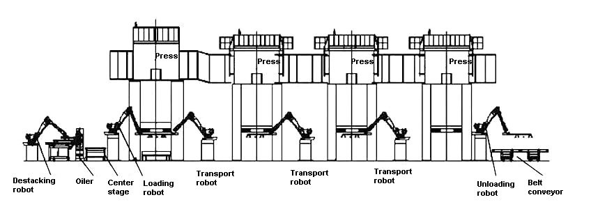
Figure 4 Automatic production line for tandem stamping
(2) Features
It has a wide range of applications and can be used in the production of various stamping components. There are no strict requirements regarding the size, shape and thickness of these components, allowing great flexibility in the production of large-scale roofing parts.
However, production efficiency is low due to the use of a robotic arm for feeding, which limits cycle time. Compared to progressive production lines and multi-station production lines, this method is less efficient.
On the other hand, mold maintenance and debugging are facilitated. Each mold belongs to a separate press, allowing independent clamping and working parameters. This means that maintenance and debugging of each mold can be carried out separately without affecting other processes.
The disadvantage is that this method requires a large production area. A traditional series production line typically includes 4 to 5 presses, taking up a significant amount of space.
How to Select Stamping Automation Production Line
When choosing the type of stamping production line, the following factors should be taken into consideration:
(1) Product material:
The type of material, its forming performance and hardness must be evaluated to determine the selection of coil or sheet forming.
(2) Material thickness:
Material thickness must be considered along with material type to determine punch press tonnage and feed mechanism support system.
(3) Monthly supply and demand:
Production capacity must be evaluated to determine the production cycle and consider the choice of an automatic line.
(4) Volume and difficulty of stamping products:
The complexity of molding and product quality requirements must be considered to comprehensively determine the mold design method and corresponding stamping automation production method.
Selection and application of stamping automation production line
Progressive Stamping Automation Production Line
According to the characteristics of each process distributed in a strip and the maximum process punches that can be achieved, it can be used for the production of small parts in the car body and can provide a high supply.
Multi-station Stamping Automation Production Line
It can be used for rapid production of medium-sized parts resistant to deformation. Symmetrical parts with complex left and right shapes, as well as products that can be grasped by the automatic lever, can be produced on the automatic line.
Tandem Stamping Automation Production Line
Due to the independent distribution of each process in each press, this production line presents the highest level of flexibility. It is ideal for the production of large and complex parts and facilitates the debugging of individual and independent production processes, making it easier to maintain high product quality control.
The characteristics of the three production lines are shown in Table 1
| Benefits | Disadvantages | Forms | |
|---|---|---|---|
| Progressive | ① High-impact, high-efficiency, high-yield times
② Small footprint |
① Poor use of material ② Only suitable for small parts ③ The mold for individual parts is large and difficult to debug. |
① Small structural parts with high demand |
| transfer | ① High level of automation efficiency ② Capable of producing a wide variety of products ③ High material utilization ④ Equipped with multiple automated security detection devices. |
① The product design process places greater demands on the joint installation of molds. ② Combined mold installation leads to inconvenient debugging and maintenance. ③ Production lines have low interchangeability and require specific molds for single-line production. |
① Beam parts, reinforcement parts, baffle parts, etc. They have a regular shape and are easy to fix, and the entire process can be distributed on the same bench.
② Parts in greatest demand |
| Tandem | ① Most applicable product types ② Flexible delivery methods for loading and unloading and processing parts ③ High interchangeability of production line ④ Easy debugging and maintenance ⑤ High material utilization |
① Large footprint
② Low production efficiency |
① Large parts and cover parts ② Parts with complicated technology and high quality requirements |
The choice between automated stamping production lines can be made based on two priorities: high throughput and high flexibility.
For a large volume of parts, an automated production line with high efficiency and high output should be selected.
If parts are complex and require advanced production technology, a flexible production line should be considered.
This is represented in a simple illustration in Figure 5.
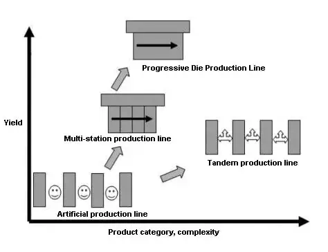
Figure 5 Special intention of 3 production lines
Based on their unique characteristics, stamping automation production lines are widely used in major automobile factories, providing robust support for the growth of the automotive industry and the rapid increase in automobile production.
Understanding and analyzing the automated stamping production line helps in selecting the stamping production method and leverages the strengths of the respective automatic lines to benefit the automotive industry.
- Progressive
- Multistation transfer
- Tandem
Abbreviated abroad::P.R.G /T.R.F/T.D.M
Which stamping automation production method should be selected is generally considered from the following factors:
- Material (material hardness and whether coils are required)
- Material thickness (punch specifications and support considerations for feeder leveling)
- Monthly production quantity (for a large number, continuous molds are available, general or less can use multistation or tandem mode)
- Difficulty stamping product shape (select the corresponding stamping automation method according to the product design mold)
Progressive die automation method
A progressive die is a type of cold stamping die that takes a strip-shaped raw material and performs multiple stamping processes simultaneously in a stamping cycle using multiple stations.
With each punch, the strip moves a fixed distance until the final product is completed.
Multi-station automation method(Transfer)
Multi-station punching technique involves arranging multiple process molds in a punching machine and utilizing the unique reciprocating movement of the punch slider to perform various operations such as stamping, punching, bending, stretching, cutting, etc., simultaneously on the installed molds on the machine tool. The robot transfers the part from one station to another during each cycle to produce a finished part.
It can be classified into two-dimensional and three-dimensional manipulators.
Three-dimensional handling method
Tandem automation method (Tandem)
Multiple punches are arranged in series to create a complete stamping production line, with each punch die corresponding to a separate forming process.
The transfer of materials between punches is done using robotic automation.
This method is mainly suitable for product lines with low production demands, limited processing steps and independent production lines that are highly flexible.
-END-