Based on the fundamental drive motor performance requirements for new energy vehicles, the types of commonly used drive motors are divided into three main categories: AC asynchronous motors, permanent magnet synchronous motors and switched reluctance motors.
Currently, each car model equipped by different automakers uses different types of drive motors.
Therefore, to choose the type of engine for a new energy vehicle, it is important to understand the structure, working principle and advantages and disadvantages of the drive motor.
I. AC Asynchronous Motor
1. Structure of AC Asynchronous Motor
AC asynchronous motor, also known as induction motor, mainly consists of a stator, rotor, motor shaft, front and rear bearings, end cover, position sensor, temperature sensor, low voltage wiring harness and wiring harness high voltage power supply.
The stator consists of the stator iron core and the three-phase winding; the rotor generally uses a squirrel cage rotor, which includes the rotor iron core and squirrel cage winding.
Depending on the engine power, the choice is made between water or air cooling methods. (Figure 1)
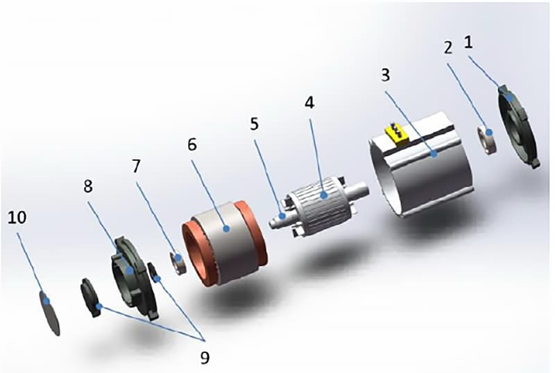
1- Front Cover
2- Front Bearing
3- Engine Housing
4- Squirrel cage rotor
5- Motor shaft
6- Stator
7- Rear Bearing
8- Rear cover
9- Position sensor
10- Sensor Maintenance Cover
2. Working principle of AC asynchronous motor
(1) Working principle of AC asynchronous motor drive
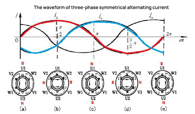
1) The stator provides a rotating magnetic field. To provide torque, the asynchronous AC motor needs to pass three-phase AC power through the stator coil, creating a continuously rotating magnetic field (with a magnetic field rotational speed of ns).
The AC asynchronous motor requires that the three-phase stator windings be symmetrical and that the stator iron core be spaced 120 electrical degrees apart. The current passing through the three-phase symmetrical winding must also be symmetrical, with the same size, frequency and phase difference of 120 degrees. The rotational speed of the rotating magnetic field is given by equation (1).
ns = 60f/p (1)
In this equation, ns is the rotational speed of the rotating magnetic field (also known as synchronous speed), r/min; f is the frequency of three-phase AC power, Hz; p is the number of pole pairs.
For a drive motor that has been designed and put into production, the number of pole pairs is fixed, so the factor that determines the rotational speed of the magnetic field is the frequency of the three-phase AC supply. As the frequency of the electrical grid in our country is f=50Hz, there is a linear relationship between the motor speed and the number of pole pairs. (Figure 2)
2) Squirrel cage rotor provides induced eddy currents. As the stator provides a rotating magnetic field, an eddy current is induced in the squirrel cage rotor conductor, as shown in Figure 3.
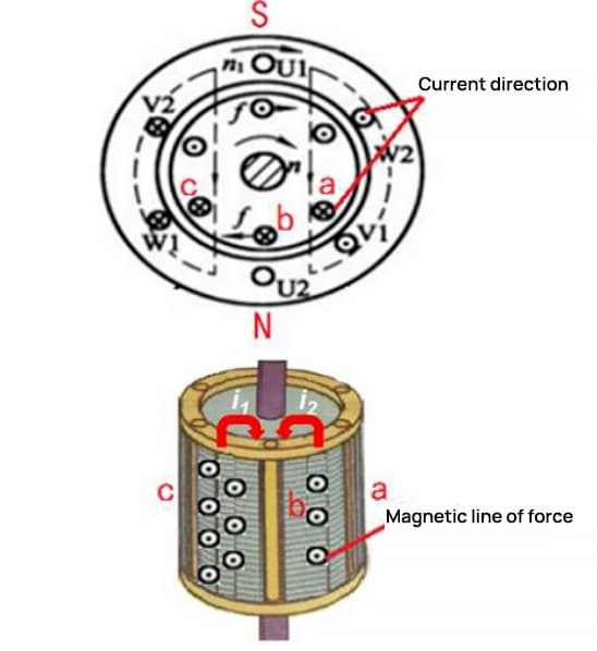
In the magnetic area between conductors c and b of the squirrel cage winding, there are external magnetic lines of force, and these magnetic lines of force are increased under the action of the rotating magnetic field.
Therefore, an eddy current i1 will be induced in conductors c, b; Likewise, the weakening of the magnetic lines of force in the area between conductor a and conductor b will induce an eddy current i2 in the conductor.
The current in conductor b, under the action of the rotating magnetic field of the stator, will cause conductor b of the squirrel cage winding to be subjected to electromagnetic force, causing the rotor to generate an electromagnetic torque and begin to rotate. The rotating rotor gradually catches up with the rotating magnetic field, rotating at a speed n slightly slower than the “synchronous speed ns” of the magnetic field.
This phenomenon, where the rotational speed of the rotor n is slightly slower than the speed of the stator magnetic field ns, is called rotor slip. This asynchronous slip allows the squirrel cage rotor conductor to continuously cut lines of magnetic force, producing induced eddy currents.
Consequently, in the rotor, electrical energy is converted into mechanical energy, ensuring a continuous external output.
(2) The Principle of Power Generation in AC Asynchronous Motors
According to Faraday's Law of Electromagnetic Induction, when a section of closed-loop conductor intersects moving magnetic field lines, an induced current is generated within the conductor, with the generated electromotive force known as induced electromotive force.
In an AC asynchronous motor, when the motor is used as a generator, the stator is energized with a three-phase current to provide the magnetic field and the rotor winding provides the conductor.
When an external mechanical force, such as a car's drive shaft, drives the rotor shaft, causing the rotor to move, if the rotor speed is greater than the synchronous speed of the stator's rotating magnetic field, the AC asynchronous motor it then acts as a generator.
The direction of the rotor that cuts the rotating magnetic field is opposite to that when it works as a drive motor, therefore the direction of the electromotive force induced by the rotor is also reversed.
During the power generation process, the motor rotor experiences an electromagnetic torque opposing the external drag force, causing the rotor speed to decrease.
3. Advantages, disadvantages and applications of AC asynchronous motors
AC asynchronous motors stand out for providing adjustable output torque over a wide range, capable of forcibly increasing output torque in short periods during acceleration or climbing. Electric vehicles powered by permanent magnet synchronous motors often employ additional gearbox mechanisms to increase torque and increase speed.
However, AC asynchronous motors have several disadvantages. Due to unilateral excitation, they require higher starting currents and more current per unit of torque produced. The stator houses reactive excitation currents, resulting in higher power consumption than permanent magnet synchronous motors with lagging power factor.
Overload conditions frequently occur during heavy-duty units. Their relatively complex structure requires high technological control knowledge, making them more expensive to manufacture, and they have comparatively lower power density.
Currently, AC asynchronous motors are commonly used as drive motors in electric vehicles developed in the United States.
II. Permanent magnet synchronous motor
1. Structure of permanent magnet synchronous motor
The structure of a Permanent Magnet Synchronous Motor comprises a stator, rotor, motor shaft, front and rear bearings, cover, cooling water channel, position sensor, temperature sensor, low voltage harness and power harness.
The stator is formed by the stator iron core and three-phase windings; the rotor consists of permanent magnetic poles and an iron core, the iron core being made of stacked silicon steel sheets.
The arrangement of permanent magnets in the rotor mainly includes surface-mounted, surface-embedded and internal permanent magnet rotors, with internal permanent magnet rotors commonly used in new energy motors. (Figure 4)
1- Front Cover
2- Front Bearing
3- Engine Housing
4- Stator
5- Motor shaft
6- Integrated permanent magnet rotor
7- Rear end bearing
8- Rear Cover (Built-in Position Sensor)
2. Working principle of permanent magnet synchronous motor
(1) Driving principle of permanent magnet synchronous motor
The rotating magnetic field is provided by the stator, produced in the same way and at the same speed as an AC asynchronous motor. The magnetic poles are powered by the rotor's permanent magnets.
Thus, the rotating magnetic field generated by the stator forms a circuit with the permanent magnetic poles of the rotor and the iron core. Following the principle of minimum magnetic reluctance, that is, the magnetic flux always closes along the path of least magnetic resistance, the rotor is set in rotation by the electromagnetic force of the rotating field.
Consequently, the permanent magnet rotor rotates synchronously with the rotating magnetic field generated by the stator, thereby driving the rotation of the motor shaft.
(2) Power generation principle of permanent magnet synchronous motor
Following Faraday's law of electromagnetic induction, a portion of the closed-loop conductor is powered by the three-phase stator windings, with the magnetic field provided by the rotor's permanent magnets.
When the external torque makes the rotor rotate, it generates a rotating magnetic field, cutting part of the conductors in the three-phase stator windings and inducing a symmetrical three-phase current.
At this point, the kinetic energy of the rotor is converted into electrical energy, and the Permanent Magnet Synchronous Motor works as a generator.
3. Advantages, disadvantages and scope of application of permanent magnet synchronous motor
The advantages of a permanent magnet synchronous motor include its small size, light weight, high power density, lower power consumption, lower temperature rise, and higher efficiency compared to asynchronous motors.
It can be designed as a high starting torque and high overload capacity structured motor based on requirements.
Permanent magnet synchronous motor synchronizes strictly and has good dynamic response performance, suitable for frequency control; Motor torque and speed can be adjusted over a wide range by changing current and frequency.
However, the permanent magnet material used in permanent magnet synchronous motors is generally a strong magnetic material of neodymium, iron and boron, which is relatively brittle and can fracture under intense vibration.
Furthermore, the use of permanent magnetic material in the rotor can lead to magnetic deterioration in motor operation and overheating situations, resulting in reduced power.
At present, permanent magnet synchronous motors are widely used in new energy vehicle engines, with the new energy markets in Asia and Europe mainly using permanent magnet synchronous motors as new energy motors.
III. Switched Reluctance Motor
1. Structure of Switched Reluctance Motor
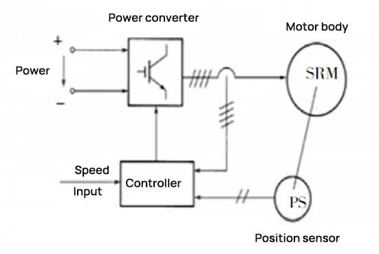
Switched Reluctance Motor (SRM) is a typical mechatronic motor, also known as “Switched Reluctance Drive System”. The engine mainly includes four components: the SRM itself, a power converter, rotor position sensors, and a controller, as shown in Figure 5.
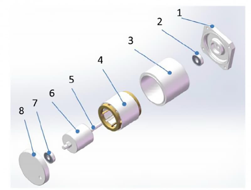
The main structure of the SRM includes the stator, rotor, position sensors, front and rear bearings, front and rear covers, and the motor housing, as illustrated in Figure 6. The stator comprises the stator core and windings.
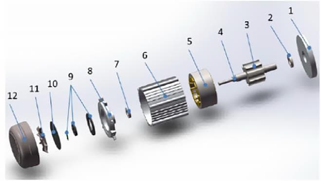
1- Front Cover
2- Front Bearing
3- Rotor
4- Motor shaft
5- Stator
6- Engine Housing
7- Rear end bearing
8- Rear cover
9- Position sensor
10- Sensor Maintenance Cover
11- Cooling fan
12- Fan end cover
Both the stator core and rotor utilize salient pole structures and are made from laminated silicon steel sheets. The protruding poles of the stator are equipped with windings, while the rotor has no windings or permanent magnets.
The 6/4-pole three-phase structure indicates that the motor stator has six salient poles and the rotor has four salient poles. The windings concentrated on two symmetrical salient poles of the stator are connected in series to form a phase, and the number of phases is equal to the number of salient poles of the stator divided by two, as shown in Figure 7 (a).
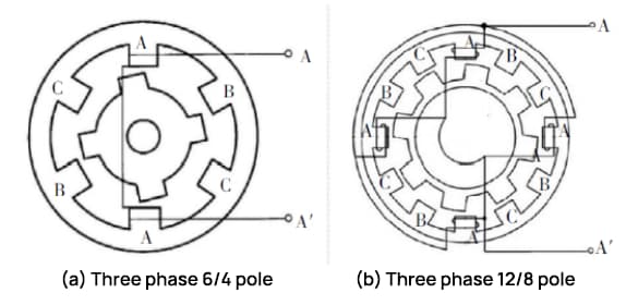
The 12/8-pole three-phase structure indicates that the motor stator has twelve salient poles and the rotor has eight salient poles. The windings on four symmetrical salient poles of the stator are connected in series to form a phase, and the number of phases is equal to the number of salient poles of the stator divided by four, as shown in Figure 7 (b).
The more phases a switched reluctance motor has, the smaller the pitch angle, the smoother the operation, and the more favorable it is for reducing torque ripple. However, control becomes more complex, leading to an increase in the number of main switching devices and costs.
The step angle calculation is shown in equation (2):
α = 360° × (Number of Stator Poles – Number of Rotor Poles) / (Number of Stator Poles)
For example, for a 6/4-pole three-phase motor, the pitch angle α = 360° × 2/(6×4) = 30°.
2. Working principle of switched reluctance motor
(1) Operating principle of switched reluctance motor drive
As shown in the working principle diagram of 12/8-pole three-phase SRM in Figure 8, when the phase A winding current controls the closing of the main switch S1, S2, phase A is energized and magnetized.
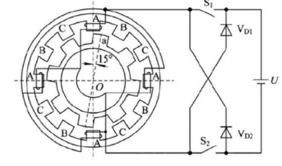
The magnetic field strength generated inside the motor forms a radial magnetic field with OA as the axis. The magnetic lines of force from this field are curved where they pass through the air gap between the salient poles of the stator and the salient poles of the rotor.
At this time, the magnetic reluctance of the magnetic circuit is greater than when the stator salient pole and the rotor salient pole coincide. Therefore, the salient pole of the rotor is influenced by magnetic attraction, which aligns the rotor pole axis Oa with the stator pole axis OA.
This generates an electromagnetic torque with the property of magnetic reluctance, causing the rotor to begin rotating counterclockwise. When the phase A current is turned off and the phase B power supply is established, the magnetic field inside the motor rotates 30 degrees.
The rotor then rotates another 15 degrees counterclockwise under the action of electromagnetic attraction. If power is supplied sequentially to the ABCA phase windings, the rotor will continuously rotate counterclockwise.
When the stator windings in each phase are energized, in turn the stator magnetic field rotates 3×30 degrees and the rotor rotates one rotor pole pitch of 3×15 degrees (i.e. 360 degrees/number of poles protruding from the rotor).
If power is supplied sequentially to the ACBA phase windings, the rotor will rotate clockwise. The direction of rotation of the switched reluctance motor is not related to the direction of the current, but is determined by the sequence of connection of the stator phase windings.
In actual operation of multiphase motors, it is also common for two or more phase windings to be energized simultaneously.
(2) Working principle of a switched reluctance generator
The operating state of a switched reluctance generator involves three conditions: the excitation state, the continuation state, and the power generation state, as demonstrated by the L-phase inductance waveform in Figure 10.
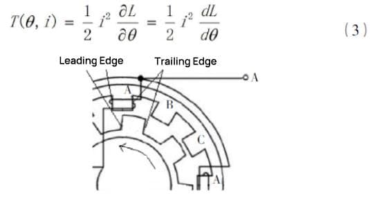
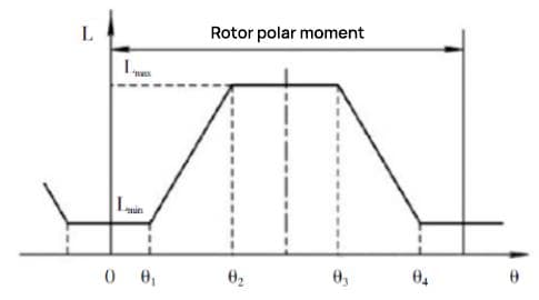
In Figure 9, angle θ is defined as the angle between the rotor tooth pole axis and the stator tooth slot axis. When the rotor tooth pole axis aligns with the corresponding stator tooth slot axis, the phase inductance is at a minimum (defined as θ=0°). The phase inductance of the winding remains constant at Lmin until the leading edge of the rotor pole meets the trailing edge of the stator pole (θ=θ1).
As the rotor continues to rotate and the rotor pole begins to overlap the stator pole, until the trailing edge of the rotor pole and the trailing edge of the stator pole fully align (at this time, θ = θ2) , the phase of the winding and inductance increases linearly in this region, reaching a maximum of Lmax.
When the rotor continues to rotate so that the leading edge of the rotor pole aligns with the leading edge of the stator pole (at this time, θ = θ4), the phase inductance remains at Lmax.
According to the basic theory of the electromagnetic field, the existence of a magnetic field is accompanied by the electromagnetic torque of the motor rotor, which can be represented by equation (3).
If the windings of the switched reluctance motor are switched on and off between θ3 and θ4, the motor works as a generator. At this time, a current forms in the region of decreasing inductance, therefore dL/dθ<0.
If current passes through the phase windings at this time, a braking torque (T(θ, i)<0) will be generated. If an external mechanical force maintains the rotation of the motor, the motor absorbs mechanical energy and converts it into electrical output, indicating that the switched reluctance motor is operating in generator mode.
3. Advantages, disadvantages and scope of application of switched reluctance motors
The advantages of switched reluctance motors are their simple and reliable structure, good starting performance, high efficiency and low cost. They offer a wide range of speed control features by varying drive, shut-off angles and voltage. However, disadvantages include substantial torque fluctuations and high noise.
Currently, they are used in some small electric vehicles, such as four-wheel electric scooters and patrol cars.
4. Conclusion
Given the distinct performance characteristics required by new energy vehicle propulsion engines, the type of drive motor selected varies between different models on the market.
This article describes the structure and working principles of commonly used new power drive motors such as AC asynchronous motors, permanent magnet synchronous motors and switched reluctance motors. This information will help in better understanding these drive motors.
Furthermore, the structure and principles of each type of engine differ, leading to a wide range of applications. According to national industrial strategic planning, research focusing on the electric propulsion systems of new environmentally friendly energy vehicles will continue to expand. Consequently, the variety and technological level of engines will also continue to advance.