- In mass production, where a large number of similar components are manufactured interchangeably, measuring the dimensions of each part will be a time-consuming and expensive exercise.
- Gauges are one of the most commonly used inspection tools in production shops for quickly checking and validating the dimensions of manufactured parts. Measurement has become an integral part of any machining process as it helps ensure the necessary degree of interchangeability between the millions of parts manufactured around the world.
- Therefore, in mass production, gauges can be used to check the compliance of the part limits with the allowable tolerance limits, rather than measuring the actual dimensions.
- Limit gauges ensure that components are within allowable limits, but do not determine actual size or dimensions.
- The gauges needed to check the dimensions of the components correspond to two sizes meeting the maximum and minimum limits of the components. They are called GO meters and NO GO (or NOT GO) meters, which correspond, respectively, to the MML and LML of the component.
- MML is the lower limit of a hole and the upper limit of the axis and LML corresponds to the upper limit of a hole and the lower limit of the axis.
Purpose of using meters:
- Components are manufactured in accordance with the specified tolerance limits, upper limit and lower limit. The size of each component must be within this upper and lower limit.
- If the dimensions are outside these limits, the components will be rejected.
- If we use a measuring instrument to check these dimensions, the process will take more time. Still, we are not interested in knowing the amount of error in the dimensions.
- It is enough that the size of the component is within the prescribed limits or not. To do this, we can make use of meters known as limit meters.
Types of meters:
Meters are classified as follows:
1. Simple meters
(i) According to the type
(a) Standard gauges (one exact copy coupling part)
(b) Limit gauges (made at the limits of dimensions)
(ii) According to the purpose
(a) Shop gauges – Shop gauges for checking dimensions after manufacturing.
(b) Inspection Gauges – Inspection gauges for checking parts prior to final acceptance
(c) Reference, master or control meters
(d) Purchase inspection gauges to check parts from other factories
(iii) According to the geometry of the tested surface
(a) Plug gauges for checking holes
(b) Pressure gauges and ring for checking shafts
(iv) According to the project
(a) Single circuit and double limit meters
(b) Single and double ended meters
(c) Fixed and adjustable gauges
2. Adjustable type feeler gauges.
3. Various meters
(a) Combined – limit meters
(b) Position meters
(c) Contour gauges
(d) Receiver meters
(e) Conical gauges
(f) Feeler gauges
Standard Gauges
Standard gauges are made according to the nominal size of the part to be tested and have the measuring element equal in size to the average allowable dimension of the part to be checked. A standard gauge should combine with some comfort.
Limit Meters:
- Limit gauges are inspection tools of rigid design, without scale, which are used to verify the dimensions of manufactured parts.
- Limit gauges do not determine the actual value of a part's inspected dimensions, but rather indicate whether the part's dimensions are manufactured within specified limits.
- These gauges are used in inspecting interchangeable parts. Typically, two hardened steel gauges are provided for each dimension to be tested.
- A 'Go' meter must pass over or through a correct feature. Checks the maximum condition of the part material.
- A 'No Go' meter must not pass over or through a correct feature. It checks the minimum condition of the part material.
The general types of limit meters are
- Plug gauges – To check internal dimensions.
- Pressure gauges and ring gauges – For checking external dimensions.
Plug Gauge:
Plug gauges are cylindrical in shape, used like a plug to inspect internal dimensions.
A simple plug gauge is used to check the size of a hole. The calibration part is made of suitable hardened, ground and polished wear-resistant steel. For heavy plug gauges, the handle can be made from light metal alloys and for smaller plug gauges, suitable non-metallic handles can be provided.
 Plug Gauge Diagram
Various types of simple plug gauges such as solid type, inserted conical type, fixed type, flat type and segmented type are available for holes ranging from smaller to larger sizes.
Ring Gauge:
Single ring gauge is a pair of gauges ('Go' gauge and 'No Go' gauge) having a measuring side with maximum and minimum shaft limit deviation to ensure shaft interchangeability.
The gauges are made of suitable, wear-resistant steel and the measuring surfaces are first stabilized, then ground and lapped.
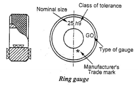 Ring Gauge Diagram
The other surfaces are finished smooth and a suitable anti-corrosion coating is applied to protect against weather conditions. The periphery of the gauge ring is serrated to provide grip during handling.
Fit (or) gap gauges:
A pressure gauge is a limit gauge, with a C-shaped structure with hardened, adjustable anvils at opposite ends, used to check diameters, lengths and thicknesses.
Types of pressure gauges:
(a) Rib type pressure gauge
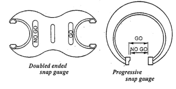
(i) Double Ended Pressure Gauge:
(ii) Single-ended progressive type:
(b) Plate pressure gauges
(i) Double-ended type
(ii) Single-ended progressive type:
(a) Rib type pressure gauge
(i) Double Ended Pressure Gauge:
This gauge is also called solid pressure gauge. The solid pressure gauge is machined and ground from a single block of metal in the shape of
a 'C' on each side. On one side is the 'Go' gauge made for the upper limit and on the other side is the 'No Go' gauge made for the lower limit of the dimension. These gauges are conveniently used to inspect sizes in the range of 3mm to 100mm.
 pressure gauge diagram
(ii) Single-ended progressive type:
In this type of pressure gauge, both openings i.e. 'Go' and 'No Go' are on the same side and are arranged in such a way that the part being measured can pass through them in sequence. The part, if within tolerance, will pass through the 'Go' (upper limit) opening (lower end) but will not pass through the 'No Go' (minimum or lower size limit) opening (upper end). These calipers are suitable for sizes ranging from 100 to 250 mm.
 single end pressure gauge
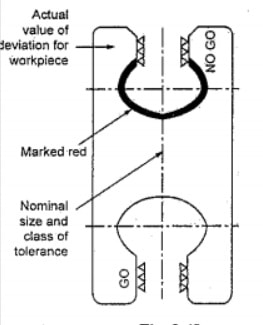
(b) Plate pressure gauges
These gauges are made of wear-resistant steel plates of suitable quality. Measuring surfaces are hardened, stabilized, ground and lapped. Other surfaces are finished smooth and all corners and sharp edges are removed.
 double end plate type pressure gauge
(i) Double-ended type:
In this type, both 'Go' and 'No Go' gauges are on both sides of the same board. They are used for sizes ranging from 2mm to 100mm. A double-ended type plate pressure gauge is shown in Fig.
(ii) Single-ended progressive type:
Here, both 'Go' and 'No Go' are on the same side of the board. On the other side, a pad of suitable non-conductive material is provided for convenient handling. These gauges are used for sizes ranging from 100mm to 250mm. A single-ended progressive type plate pressure gauge is shown in Fig.
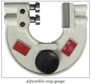
Adjustable type feeler gauges:
Adjustable type feeler gauges are in the shape of a horseshoe structure with their adjustable calibration anvils. The anvils are adjusted using independent screws with a fixed thread. The opening clearance is set to the required limit using slide gauges and the screws are locked into position. Adjustable feeler gauges can be reset to compensate for wear or reset to measure a different dimension. They offer the flexibility to build our own caliper within any size within the specified range. It is preferable where the number of components to be inspected is less, but the range of sizes to be inspected is greater.
 adjustable pressure gauge
Various meters:
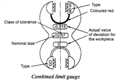
Combined Limit Meter
A single plug gauge used to inspect the upper and lower limits of cylindrical holes is called a combined limit gauge.
 combined caliber
Position Meter
A position gauge is used to check the position of a feature on the part relative to another reference point or surface. The shape and design of a position gauge depends on the feature to be checked. The design of the position gauge can be based on the operator's feeling or the principle of observation. When in contact with the 'Go' side, no light will pass between the reference surface and the meter surface, and when in contact with the 'No Go' side, light will pass.
 position meter
Contour gauges
Contour gauges are also called profile gauges used to check the dimensional accuracy and cross-sectional shape of a surface. These meters are made with a profile similar to that of the work.
A contour gauge consists of a set of pins (made of steel or plastic) firmly joined together in a frame so that they are parallel to each other and in the same plane. Thus, when the meter is pressed against an object, the pins that can move independently adapt to the shape of the object. Now the gauge can be used to draw the profile or copy it to another surface.
Examples of simple contour gauges are radius gauges for gear tooth profiles, forming tool profiles, thread pitches, etc.
Conical gauge:
- Taper plug gauges are used to check taper holes. It has two verification lines. One is a GO line and the other is a NOGO line.
- During work checking, the NOGO line remains outside the hole and the GO line remains inside the hole.
- There are several types of taper plug gauges available as shown in fig. As
1) Taper plug gauge — simple
2) Conical plug gauge — with tang.
3) Simple Taper Ring Gauge
4) Conical ring gauge – with tang.
 conical gauge diagram
Line meter:
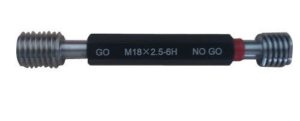
- The threads are checked with the help of thread gauges.
- To check internal threads (nuts, bushings) plug thread gauges are used. Similarly, ring thread gauges are used to check external threads (screws, screws).
 thread gauge
Form Gauges:
- Form gauges can be used to check the profile contour of a workpiece.
- Form gauges are nothing more than template gauges made from sheet steel.
- A profile gauge can contain two contours that indicate the boundaries of a profile
 shape gauge diagram
Screw Pitch Gauge:
- Screw pitch gauges are used to immediately check thread pitch. These are basically the everyday tools used to choose the screw you need.
- The number of flat blades with different pitches are articulated on a support. The step value is marked on each blade.
Radius and fillet gauges:
- The bending radius can be measured using these gauges. The radius can be external or internal.
- Depending on the type of radius to be measured, the end of the blade is made with a concave or convex profile.
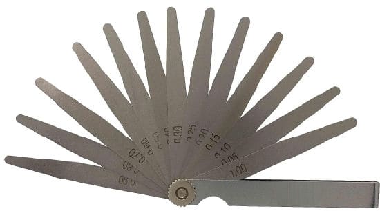
Feel Meter:
- Feeler gauges are used to check the clearance between mating surfaces.
- They are mainly used to adjust valve clearance in automobiles.
- They are made from 0.03 to 1.0 mm thick and 100 mm long. The blades are pivoted on a support.
 feeler gauge
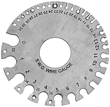
WIRE meter:
Wire gauge is used to measure the width of sheets and diameter of wires. It is available in the form of plates. Different sized slots are available on a board to measure preferred thickness or diameter. These grooves, previously numbered, are available from gauge 1 to 30. The sheets and wire that are to be calculated pass through these grooves and it is verified that they would not be movable and together they must touch the groove. Currently, the number in the slot is its caliber value.
 wire gauge
Pin Gauge:
This gauge is the diameter of large holes that cannot be measured simply by micrometer or vernier and so on. It can be measured by means of a pin by spherical ends, the length of which is slightly less than the micrometer to be measured the pin is located in the hole by its ends in
contact on the surface of the hole, its axis being a chord of the circle. Keep one end in contact with the surface of the hole, the other end is brought transversely to make contact on the other side. The distance between the two contact points is measured and, from this dimension and the length of the gauge pin, the diameter of the hole is determined.
Points to remember in Gauge Design
- The shape of the 'Go' gauges must be a replica of the shape of the corresponding parts.
- 'Go' gauges must allow several related dimensions to be checked simultaneously.
- During inspection, Go meters must always be placed in conditions of maximum impassibility.
- 'No Go' meters are for checking a single element of the resource at a time.
- 'No Go' meters must always be placed in conditions of maximum passability during the inspection.
Gauge material
The material used in the manufacture of meters must meet the following requirements:
1. The material used to manufacture the meters must be hard and wear-resistant for a long service life.
2. Must be able to maintain dimensional stability and shape.
3. It must be corrosion resistant.
4. It must be easily machinable to obtain the necessary degree of precision and surface finish.
5. It must have a low coefficient of expansion to avoid temperature effects.
High carbon steel
- It is the most suitable and cheapest material used in the manufacture of meters.
- It can be heat treated appropriately to provide stability and high hardness.
- It can be easily machined with a high degree of precision.
Mild steel
- Mild steel gauges are best suited for larger gauges.
- They are suitably heat treated by carburizing to the required depth and then have their working surfaces hardened to allow for final sanding and finishing.
- After hardening, internal stresses are relieved to improve stability.
Chrome gauges
- Chrome gauges are very popular and widely used for measurement.
- Chrome coating makes the meter surface very hard and resistant to abrasion and corrosion
- It is also very useful in recovering worn meters. To measure aluminum or other materials with abrasive action, chrome-plated gauges are widely used.
Glass
- Glass gauges are not very popular, although they have good wear and corrosion resistance properties.
- The problem with these meters is that they are easily damaged or broken if dropped.
- They are not affected by temperature changes and have a very low coefficient of thermal expansion.
Invar
- Although Invar, which contains 36% nickel, has a low coefficient of expansion, it is not suitable for a long period.
Eliminate
- Elinvar has 42% nickel, is more stable than Invar and also has a low coefficient of expansion.
Meter tolerance (meter manufacturer tolerance)
- Gauges, like any other component, cannot be manufactured to your exact size or dimensions.
- To accommodate these dimensional variations, which arise due to limitations of the manufacturing process, operator skill, etc., some tolerance must be allowed in gauge manufacturing.
- Thus, the tolerance allowed in gauge manufacturing is called gauge manufacturer's tolerance or simply gauge tolerance.
- Normal practice is to consider the gauge tolerance as 10% of the working tolerance.
Wear tolerance
- During inspection, the NOT GO side must not enter or pass through.
- The NOT GO meter fully engages the work and therefore does not suffer any wear. Therefore, there is no need to predict wear in the case of NOT GO meters.
- The GO side of the meter should enter the hole or simply pass over the shaft under the weight of the meter without using undue force.
- During inspection, the measuring surfaces of the gauge constantly rub against the contact surfaces of the workpiece. Therefore, GO gauges suffer wear on the measuring surfaces and thus lose their initial dimension. Accordingly, wear allowance is provided for GO meters to prolong their service life.
- The wear allowance provided for the GO gauge is added in the opposite direction of wear. This tolerance is added for a plug gauge and subtracted for a ring or gap gauge.
- A wear tolerance of 10% of the gauge tolerance is widely accepted in industries.
Application of meters:
1. Thread gauges
2. Form Gauges
3. Serew step meters
4. Radius and fillet gauges
5. Feeler gauges
6. Plate gauge and wire gauge